chrisgre
New member

Hi folks, I apologize in advance, this is going to be completely obvious to a lot of people, bear with me?
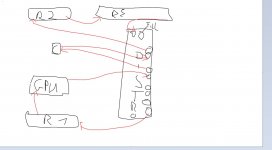
I have a 360 distro plate. It is the variety with the pump on the left side, and the g1/4 ports (mostly) on the right.
In the manual, the combination of the arrows and labels are what are confusing me.
At first, I thought the arrows were indicating direction of flow, but the Drain port has the arrow pointing towards it, which would be the opposite of draining.
Here's what makes more sense to me, and I hope someone can confirm:
Then the profile:
TO FLOOR (because you forgot bucket) || Drain ---- o
Is this the correct interpretation?
I really don't know much about fluid dynamics, but I'm assuming that the long, 4-port SLI chamber should only have water flowing INTO it, and you really wouldn't want to.. for instance, have an output from port 3 of the CLI chamber to something (another rad, a flow meter, etc) with the output of that thing flowing INTO port 4 of the SLI chamber. I'm really not able to explain why I think you _shouldn't_ do this, but in my head it translates into something like "no chris, that will confuse the water".
Apologies for the text wall, I appreciate someone setting me straight. Thanks peoples!
I have a 360 distro plate. It is the variety with the pump on the left side, and the g1/4 ports (mostly) on the right.
In the manual, the combination of the arrows and labels are what are confusing me.
Code:
Radiator IN <---- o o o <---- Radiator Out
CPU OUT     ----> o
CPU IN.     <---- o
GPU OUT     ----> o
                  o
                  o
                  o
SLI Config <----  o [Pump]

On the profile view, there is a:

Drain Port ----> o

This how I interpret the mirror:

Radiator Out ----> o o o ----> Radiator IN
                       o <---- CPU OUT
                       o ----> CPU IN
                       o <---- GPU OUT
                       o
                       o
                       o
                [Pump] o ----> SLI Config
At first, I thought the arrows were indicating direction of flow, but the Drain port has the arrow pointing towards it, which would be the opposite of draining.
Here's what makes more sense to me, and I hope someone can confirm:
Code:
TO RAD ----- o o o ---- FROM RAD
                 o ---- TO CPU
                 o ---- FROM CPU (nice n' warm)
                 o ---- TO GPU
                 o ---- FROM GPU [opt]
                 o ---- FROM GPU [opt]
                 o ---- FROM GPU [opt]
          [Pump] o ---- FROM GPU [opt]
Then the profile:
TO FLOOR (because you forgot bucket) || Drain ---- o
Is this the correct interpretation?
I really don't know much about fluid dynamics, but I'm assuming that the long, 4-port SLI chamber should only have water flowing INTO it, and you really wouldn't want to.. for instance, have an output from port 3 of the CLI chamber to something (another rad, a flow meter, etc) with the output of that thing flowing INTO port 4 of the SLI chamber. I'm really not able to explain why I think you _shouldn't_ do this, but in my head it translates into something like "no chris, that will confuse the water".
Apologies for the text wall, I appreciate someone setting me straight. Thanks peoples!


