Project Hush!

Greetings everyone! This is a project that was originally started back in 2009. It was got to a functional working state, with PC components installed, but then life got in the way before completing it... I was moving around the country at least annually for work, and the case got put in storage. Over the last year I have been finishing it...

A big thank you to Alphacool (and to Christopher at Alphacool) for kindly offering to sponsor the project!

Well, here's the build logs so far, starting from the beginning.. This might take a while! I will post the progress so far, adding more posts of the build over the coming days, so please do come back to read more!

------
July 2009:

Hello all. I've started making a large passive radiator/case. I've been working on it for a while, but since the design is quite complicated I thought I'd wait until it got to a recognisable, likely to work(!) stage before starting the build log.

I have had an innovatek Konvekt-o-matik before selling it on members' market, but from what I've heard you really need a shedload of them to handle high heatloads. Plus, they're expensive (~£80/6tubes), bulky and the design is flawed in my opinion - aluminium, made for 8mm ID tubing, and by their design the more of them you add the larger the pressure loss - 8mm inlet splits to 8mm tubes running in parallel.

So I figured I'd make my own;
:)


copper,
designed for 7/16" or 1/2" tubing,
minimise pressure loss by matching resistance of the tubes to 1/2" tubing,
massive amount of surface area (since it's the equivalent of an Aga it needs to have headway for extra heatload),
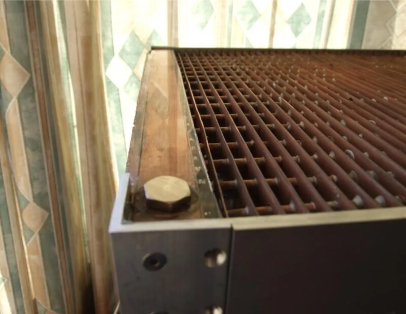
wide fin spacing and compact enough to be self-contained within a case.

The case is going to be approximately 45cm wide x 40cm deep x 46cm tall + height of castors. So it's slightly smaller than a mountain mods UFO (45x45x45)

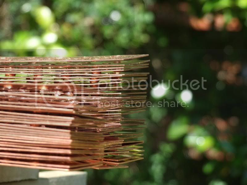
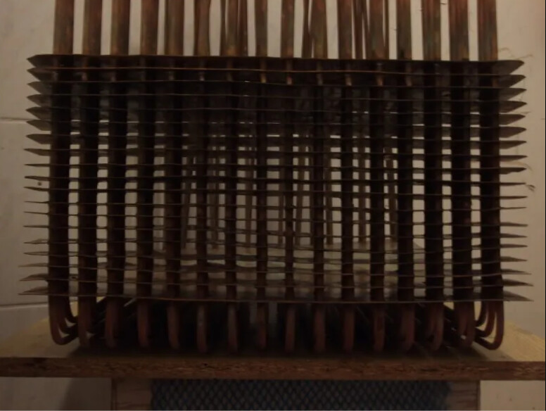
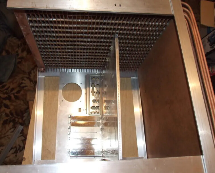
The top, far side of the case (the non-window side panel on a normal case) and the bottom will be made up of a large finned copper radiator, hopefully with enough surface area and passive airflow to run completely passive, with air rising up through the case.
:)
I wish I was competent enough with google sketchup to draw a detailed plan, but it just seems a nightmare because of the design, so I'm afraid I've largely stuck to hand-drawn sketches. Here's a very rough idea of what the passive radiator element of the case will look like.

d5c1101c by Tom ., on Flickr


Initially I was going to use 30 metres of standard 15mm outer diameter half-hard pipe used in home plumbing and flatten it as in normal watercooling radiators, but after buying a small sample (a gentle elbow bend) and trying to flatten it I realised it's very tricky to get an even inner channel, and it would take forever to flatten 30m of the half-hard stuff...


7f68d996 by Tom ., on Flickr


87d66dc2 by Tom ., on Flickr

After scouring around to find a cheap source of soft copper pipe I found on ebay what was listed as 9m of soft 15mm outer diameter, 0.4mm-thick-walled copper pipe used as gas lines in boats and motorhomes, and being the only bidder got it dirt cheap.
:)
. I picked up an adjustable pipe cutter (3-22mm) for a few quid and measured and cut 130cm lengths. Turns out I was sold around 14m, so had 10 x 130cm, and an offcut.


Unfortunately, though slightly easier than the the half-hard copper, the walls of the stuff I got was 1.5mm so it was still a nightmare, and still came out uneven in cross-section and took ages to flatten. I also found it's expensive stuff to get any more - about £80 for 25m. I'll find a good use for it later on though.

22168a7d by Tom ., on Flickr

So, time for plan B. I managed to find a site selling 10m x 6mm outer diameter, 4.8mm inner diameter soft microbore copper tubing, so I picked up 6 rolls for ~£42 inc p&p


538124f2 by Tom ., on Flickr


cd85c9a3 by Tom ., on Flickr

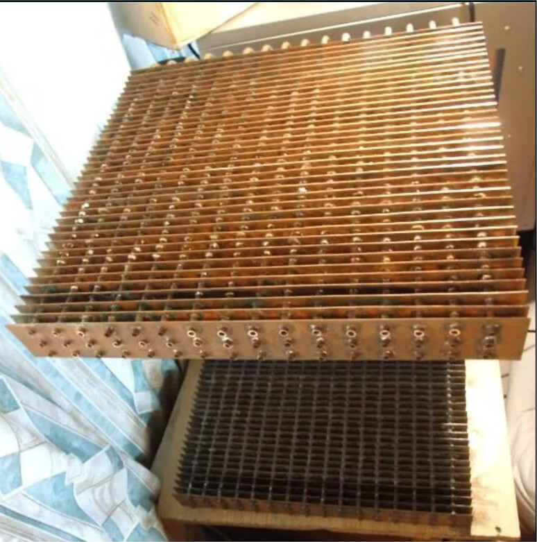
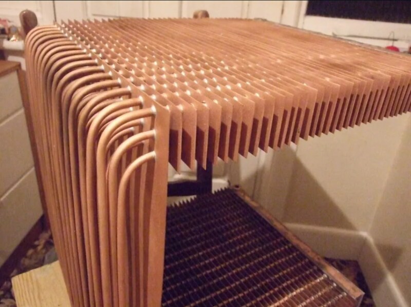
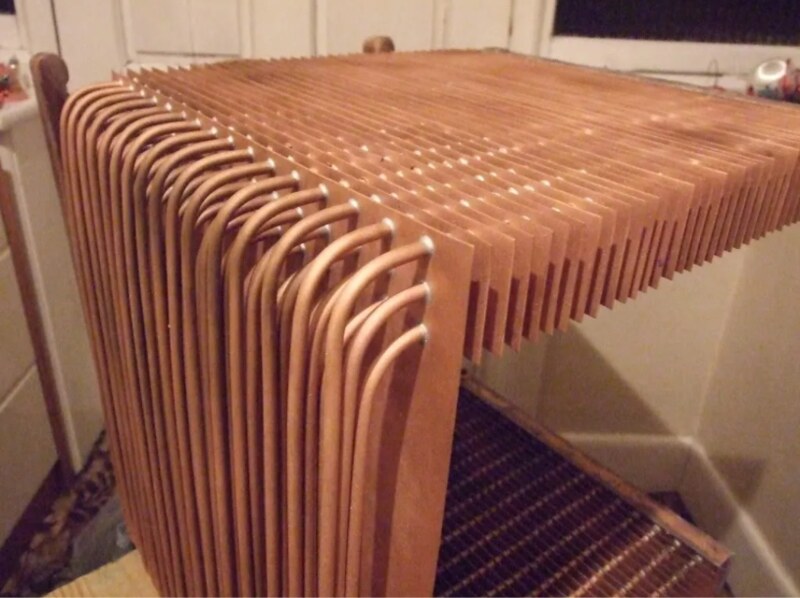
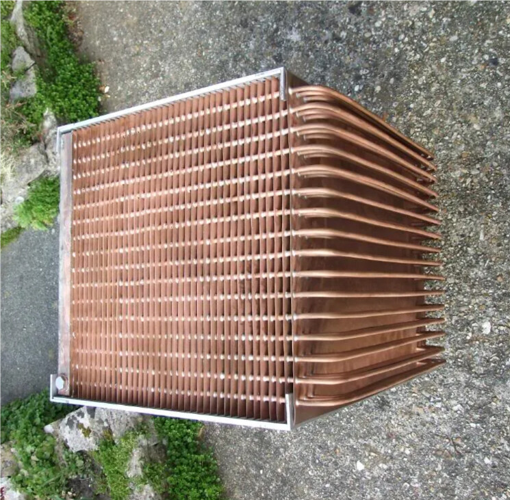
I then unrolled them, measured and cut into 48 lengths - 16 x 120cm, 16 x 125cm and 16 x 130cm - the difference is because the 48 tubes will be arranged as so, so the outer tubes need to be a bit longer:

1255a9c7 by Tom ., on Flickr


a330a423 by Tom ., on Flickr


3333fbf0 by Tom ., on Flickr

The microbore copper is so soft it's very easy to bend and straighten, though it's tricky to get 130cm lengths completely straight. It work-hardens and quickly becomes difficult to bend, though it can be annealed again by sticking it over a gas hob.


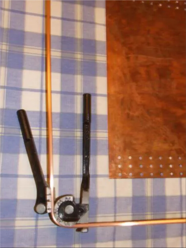
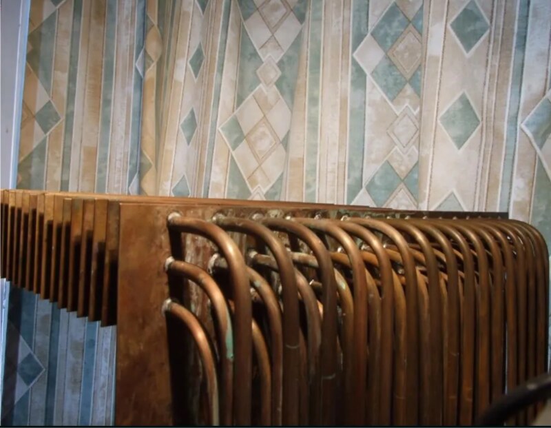
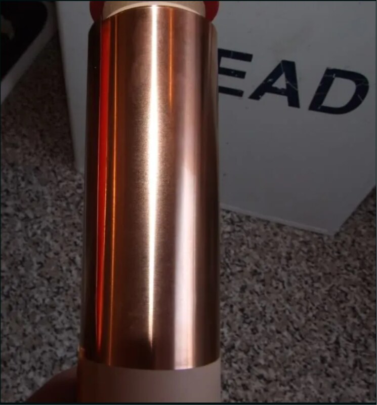
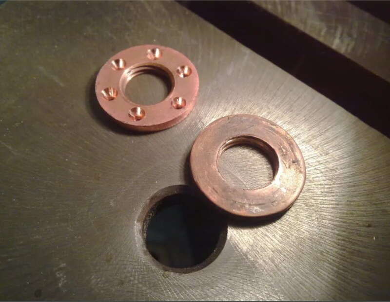
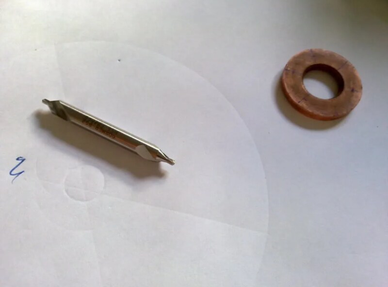
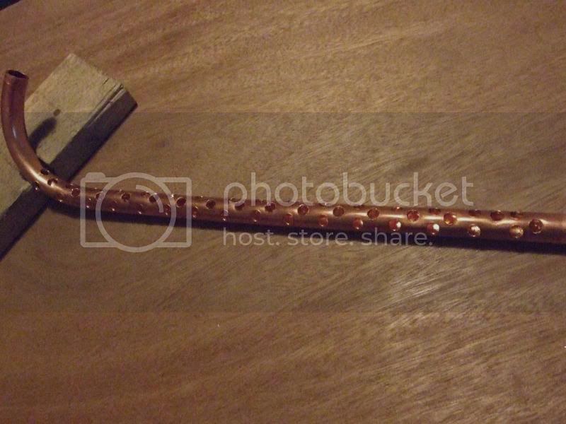
Anyhow, I had originally planned to use some of the 15mm pipe I had for the end pipes distributing the water to the 6mm copper tubes. It has a 12mm inner diameter so is a pretty good match for either 7/16" or 1/2" tubing.. After straightening one of the 130cm lengths I bent it to a hook shape over a rolling pin, which was quite tricky. I then cut it to a rough length and measured out the 48 x 6mm holes for the microbore pipe to connect to.

The pipes will have to do a bit of bending at the ends, but hopefully with the small bore pipebender I got this won't be too much trouble, though in reality it'll probably be very very frustrating, since the pipe needs to be bent after the copper fins have been pushed into place.

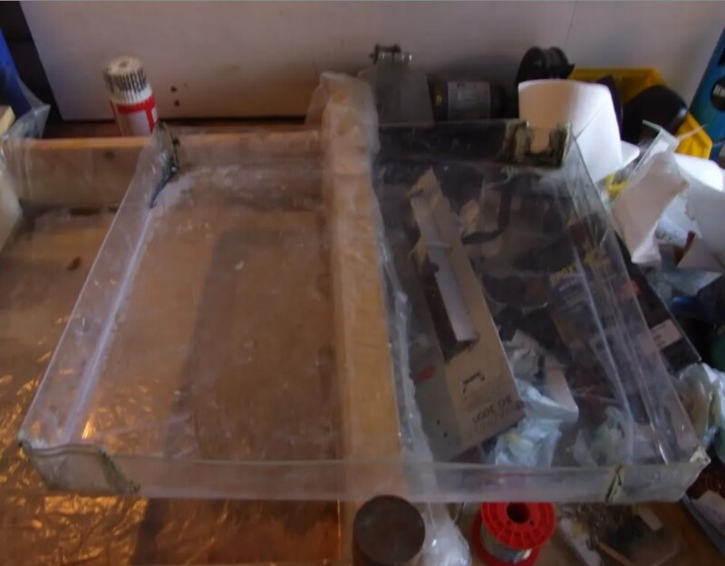
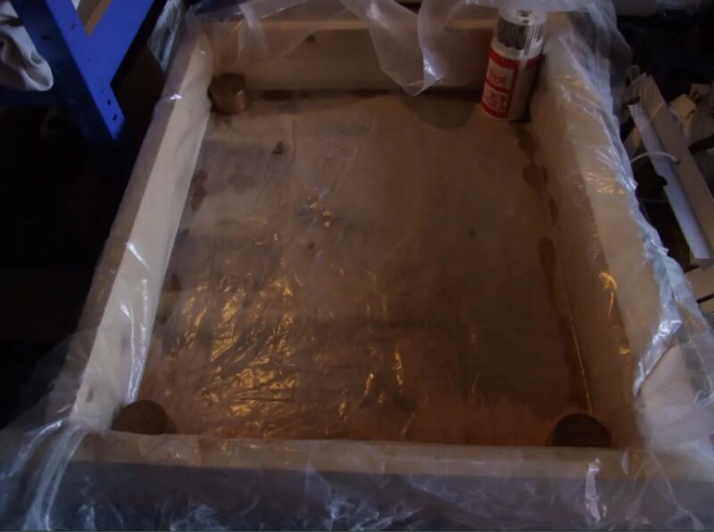
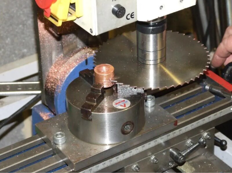
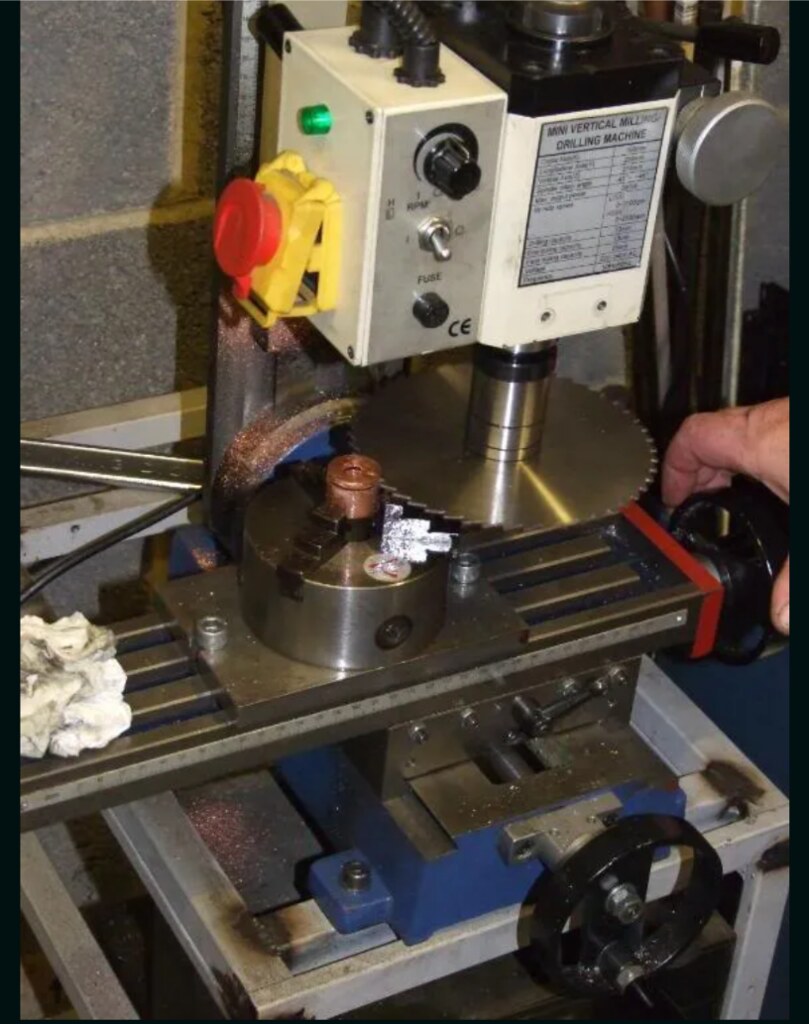
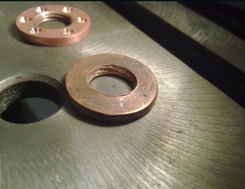
After lots and lots of drilling here are the radiator end pieces. This would have been so much easier if I had a bench drill and a vice, but as I didn't at this stage I had to improvise:


41c5ba2f by Tom ., on Flickr


b918967b by Tom ., on Flickr

a7cae1ed by Tom ., on Flickr

Plan for pipes joining distributor end tube - side view

03be0139 by Tom ., on Flickr
 
After all that drilling my plans changed (always the best way for a project to go horribly wrong). I managed to source some cheap copper sheet for around a quarter of the going rate from shopping around, and for a small extra charge the seller was even willing to cut it with a metal shear into lots of 395mm x 50mm strips for the heatfins. So the dimensions of the whole thing changed, and the drilled pipes were now the wrong size. Ho hum.

I now plan to instead use a plenum akin to those in standard pc radiators. They serve a purpose in allowing a reservoir of water so that water going down the tubes doesn't cause unequal flow between pipes at the inlet end compared to the other. More importantly, it would be easier to make rather than many cramped, fiddly bends for the tube ends.

Here's a picture of the copper. It had been left lying around in a scrapyard for God knows how many years, and was a bit scratched here and there, but should clean up nicely enough.

1f7f673e by Tom ., on Flickr

In the pic are a 39.5cm x 45.5 cm x0.9mm copper sheet for the side wall the tubes go through, 63 of 39.5cm x 5cm x 0.9mm copper strips to be used as heatfins, and 16 of 7.5cm x 39.5cm strips (additional 39.5cm x 5cm heatfins have since been cut from them). There's also some copper bosses (solid cylinders) that I nmay put to good use.


After cleaning

5d966567 by Tom ., on Flickr

95b44e13 by Tom ., on Flickr

abe41b14 by Tom ., on Flickr

d2500e81 by Tom ., on Flickr
 
Project: Hush! - Updated 4/4/10

I then needed to drill 48 x 6mm holes in each of the copper fins and the copper wall. This took a while.


92230e3f by Tom ., on Flickr

960b007b by Tom ., on Flickr

I initially tried using G-clamps and my bench drill and ran into several problems. As the holes were drilled, they pushed a cusp through, deforming the clamped stack. Whilst the cusp/sleeve from drilling is actually useful for soldering and heat transfer, it introduces inaccuracy in the drilling. So I made a jig for putting the copper strips in for drilling.

JIG FOR DRILLING

89d67a90 by Tom ., on Flickr

a5016651 by Tom ., on Flickr


494a3a03 by Tom ., on Flickr

0df01084 by Tom ., on Flickr

6f625e99 by Tom ., on Flickr

Sadly the bench drill I have is only 180W, and so lacks the torque to drill large metal holes, so I switched to using an 810W hand drill in a heavy duty drill stand, which allows accurate vertical drilling.

18e13694 by Tom ., on Flickr


7b66552f by Tom ., on Flickr


PICS OF DRILLING

After doing some reading up on natural convection and passive heatsink design, I came across a problem sheet set for engineering students on how to optimise the fin spacing for a passive radiator, from a book by a couple of heat transfer professors, and even better, the software it ran on was freely available on the web. So, using the software, I adjusted the parameters to model my heatsink as best I could.

4e0121b4 by Tom ., on Flickr

Passive heatsinks rely on natural convection, and this requires the free movement of air over the fins. The fins are much more effective spaced much further apart than in air-cooled heatsinks (~2mm for a Thermalright Ultra Extreme) or even the most sparsely-finned watercooling radiators (~1fin/3.125mm or 8fpi for an RX XSPC radiator).

The simulator models a given width, height and depth of passive heatsink at a given input heatload, and plots the heat transfer of a given fin, and the total heat transfer of all fins combined, at varying fins spacings.


91975eb1 by Tom ., on Flickr


So, whilst the heat transfer for a single fin increases up to a certain point, increased fin spacing means fewer heatfins overall. There's a balance between the two, giving an optimal spacing for a given heatload:

From the simulator there's also another interesting trend - as the input heatload decreases, the optimal fin spacing (fin-pitch) increases, which means I need to optimise the heatfin spacing for the air-water delta T I want to aim for...

bac48c73 by Tom ., on Flickr

The simulator mathematically models a heatsink made from two copper plates held at a set temperature with heatfins that run perpendicular between them, so it's not exactly what my heatsink design is, and in adapting it to model my design I'm not entirely sure how to adapt mine to it, since my design has 48 6mm outer diameter, 4.8mm inner diameter tubes running through the heatfins. I'm unsure as to whether I should adapt it so I equalise the inner heatpipe surface area (4.8mm)to the end-heatplate- to-heatfin surface area in the model, or the outer heatpipe (6mm) surface area... Hope that makes sense!

I altered the parameters to assume just two end heatplates as in the original design, to give a conservative estimate of the performance, and the heatfin spacing (1 heatfin per 10mm, so about 9.1mm between each heatfin). This gave around a 300w heat transfer for a delta of 10C between the air (20C) and the heatpipe/water temperature (30C). But as I say, this is hopefully the worst-case scenario (though the model uses copper-copper joins rather than soldered joints...). A point to note is that the model only calculates the heat transfer from the heatfins - it excludes the heat transfer from the copper tube surface area (~11,000cm^2) and the copper wall (~3,600cm^2).

PIC WORSTCASE SCENARIO (spacing of 10mm on the x-axis)


Adjusting the model to equalise the end plate-to-heatfin surface area in the model with the tube-to-heatfin surcace area gives silly numbers (~560W heat transfer at a 0.5C Delta T, 400W for a 0.4C Delta T).

The real performance will probably lie somewhere inbetween - whilst the best case scenario is probably largely correct in terms of more accurate surface area for the water to transfer heat to the pipes and fins, the model assumes continuous copper joints, and inaccuracies in hole size and loss from soldered joints (~96% tin/ 3.5%Silver/0.5% copper solder) will no doubt lower performance.

Anyhow, enough hypotheticals, here are some pics of where the project is up to at the moment.


7a932254 by Tom ., on Flickr


89f44b6a(1) by Tom ., on Flickr
 
Last edited:
After drilling the heatfins I found the holes were marginally too small, using a digital Vernier, in th order of a few hundredths of a mm.

PIC OF DIGITAL VERNIER

498880be by Tom ., on Flickr

So I decided to erode them down slightly by putting them in a drainpipe full of vinegar and harpic toilet cleaner (since it's hydrochloric acid based). I must say, looking through household detergent ingredients for the strongest acid in the supermarket made me feel like a terrorist!

Screenshot_20221018-151300_(1) by Tom ., on Flickr

PIC OF TUBES IN DRAINPIPE

Screenshots_2022-10-18-15-14-37 by Tom ., on Flickr

Screenshots_2022-10-18-15-15-11 by Tom ., on Flickr

PIC OF TUBES OUT OF DRAINPIPE

Screenshots_2022-10-18-15-15-48 by Tom ., on Flickr


I then used a microbore pipe bender to make the bends in the pipe. It's a handy little tool, but unfortunately they put far too much paint on it, meaning the measuring bits and the 6mm tube channel was too small, meaning the tube wouldn't get equal pressure around it when bending and would deform too much for my liking. After a quick bit of paintstripping with Nitromors I bent the tubes for insertion into the copper wall. This was a bit fiddly; in order for the bends to line up exactly with the drilled holes I needed to know amount of length the bend took. After a few annoying mishaps, annealing and restraightening I got the tubes bent accurately.

Screenshots_2022-10-18-15-16-22 by Tom ., on Flickr

Screenshots_2022-10-18-15-16-55 by Tom ., on Flickr

Screenshots_2022-10-18-15-17-34 by Tom ., on Flickr

Screenshots_2022-10-18-15-18-14 by Tom ., on Flickr
 
Last edited:
After inserting all the tubes I could then start putting the heatfins on.

I ran into a bit of a problem when putting the fins on - they're a tight fit and the smallest angle off horizontal, or pipe angle off vertical means they can be tricky to get on. It's a bit of a trade-off between tight fitting fins with minimal gaps (less solder and better heat transfer) and ease of putting the thing toether. The fins are pretty tight, and in gently hammering them ona few of the tubes were pushed too far down, which you can se in the pic. Luckily, using the pipe cutter without the cutting blade inserted it's possible to grip the tube and push it back through the heatfins.

PIC OF PIPE CUTTER MINUS BLADE


Screenshots_2022-10-18-15-36-18 by Tom ., on Flickr

There's only 11 heatfins on in various temporary positions (finished article will have 74 fins);

PICS WITH HEATFINS

Screenshots_2022-10-18-15-36-54 by Tom ., on Flickr

Screenshots_2022-10-18-15-37-28 by Tom ., on Flickr


Screenshots_2022-10-18-15-38-03 by Tom ., on Flickr

Screenshots_2022-10-18-15-38-46 by Tom ., on Flickr

I've just got the solder and flux and need to make a watertight box tonight to deoxidise the copper in a vinegar bath before, and after soldering them with a propane/butane blowtorch, since it'll oxidise all the surrounding copper. Anyone know of a place I can get lots of cheap, relatively strong acid? Not sure where to get it and any regulations - was told by a car bits shop that they can't sell battery acid (~35% sulphuric acid) these days. I could probably make do with distilled vinegar but it'll be expensive for the amount I need and take a long time as it's weak.

Any questions just ask.
 
Last edited:
UPDATE 1

Roughly how the removable motherboard tray will sit (looks a little tighter height-wise than it will be due to the top pipes being a little bent down atm). The PSU will sit behind at the bottom, fan facing down.

Screenshots_2022-10-18-16-10-38 by Tom ., on Flickr

A sheet of 2mm styrene that was lying around:

Screenshots_2022-10-18-16-11-25 by Tom ., on Flickr

Heatgun:

Screenshots_2022-10-18-16-11-53 by Tom ., on Flickr

Bending:

Screenshots_2022-10-18-16-13-25 by Tom ., on Flickr

A quick and dirty tray to bath it in. So quick and dirty that it leaked, so it has an outer box lined with plastic sheet a mattress came in - now it's in the styrene tray to avoid cutting up the plastic lining:

Screenshots_2022-10-18-16-14-02 by Tom ., on Flickr

Screenshots_2022-10-18-16-14-25 by Tom ., on Flickr

Deoxidising:

Screenshots_2022-10-18-16-15-58 by Tom ., on Flickr

Shiny:

Screenshots_2022-10-18-16-16-28 by Tom ., on Flickr

Making solder slinkies.

Screenshots_2022-10-18-16-17-33 by Tom ., on Flickr


After cutting to solder rings - not sure how many are in the bag, probably a thousand or so.

Screenshots_2022-10-18-16-18-07 by Tom ., on Flickr

Blowtorch - gets up to temperature okay.

Screenshots_2022-10-18-16-18-44 by Tom ., on Flickr

Various bits for putting fins on and soldering:

Screenshots_2022-10-18-16-19-24 by Tom ., on Flickr

Fin in place with 9mm thick wooden spacers for straightening the fins (they need to be hammered gently into place and deform a little in the process)

Screenshots_2022-10-18-16-20-13 by Tom ., on Flickr


Solder rings put around the pipes - it's quicker to put them on like this, with a fin above, near the pipe ends, as it made putting the fins on a lot quicker.

Screenshots_2022-10-18-16-20-45 by Tom ., on Flickr

Solder rings after tightening with needl-nosed pliers (surprisingly quick and easy).

Screenshots_2022-10-18-16-21-25 by Tom ., on Flickr

A freshly soldered fin on top: The fins are a bit rainbow coloured from scale slowly being removed by the weak acid bath - hopefully it'll all go - the bottom fins are quite pink. It was pretty disconcerting to see the shiny copper scale up and get covered with burnt flux, as it didn't seem to get removed at first. I'm a bit concerned about the acid possibly attacking the solder joints - I may switch to cleaning it only at the end when all in place and using a fine wire brush to clean the pipe before soldering.

Screenshots_2022-10-18-16-21-57 by Tom ., on Flickr

Screenshots_2022-10-18-16-23-00 by Tom ., on Flickr

Screenshots_2022-10-18-16-23-34 by Tom ., on Flickr

Unfortunately I couldn't correct the bend that got pushed too far through (3rd from the left at the bottom). A few of the first fins are a little bent as well, though they'll be mostly out of sight behind the motherboard tray.
 
Last edited:
(July 2009)
Time for an update.

I changed the method by which I put the fins on;- before I had deooxidised the copper pipe prior to putting new fins on, now I instead changed to using strips of 120 grit wet'n'dry with sellotape on the back to strengthen, which I used to sand about 4cm of the pipes, flux and slide fins on (I had already filed the holes of):

PIC OF SANDED PIPES

Screenshots_2022-10-18-17-23-21 by Tom ., on Flickr

Screenshots_2022-10-18-17-23-43 by Tom ., on Flickr

All the heatfins are now on, and the pipes have been trimmed down.

PICS OF MONSTROSITY

Screenshots_2022-10-18-17-23-59 by Tom ., on Flickr

Screenshots_2022-10-18-17-24-13 by Tom ., on Flickr

Screenshots_2022-10-18-17-24-29 by Tom ., on Flickr


Screenshots_2022-10-18-17-24-47 by Tom ., on Flickr

Screenshots_2022-10-18-17-25-14 by Tom ., on Flickr

Screenshots_2022-10-18-17-25-33 by Tom ., on Flickr

I've decided to make the manifold/plenum from copper - it'll have an inner box made from thin copper (0.152mm thick) joined to the end fin by solder paste, and strengthened with some of the thicker 0.9mm thick copper made from 4 leftover copper strips I had.

My friend Robin has some nice tools and machines, so I asked him to maked the inlet, outlet, fillpoint and drain port for the radiator from the 25mm diameter copper bosses I had.

PIC OF LATHE

Screenshots_2022-10-18-17-26-47 by Tom ., on Flickr

After making 11.8mm holes with the lathe the copper bosses were tapped on the lathe with a BSP 1/4 tap, cut with a circular saw mill bit and then fly-cut on the mill to give a beautiful smooth shiny surface, which doesn't really come across in the photos:

MACHINING


Screenshots_2022-10-18-17-26-58 by Tom ., on Flickr

Screenshots_2022-10-18-17-27-15 by Tom ., on Flickr

Screenshots_2022-10-18-17-27-26 by Tom ., on Flickr


Screenshots_2022-10-18-17-27-39 by Tom ., on Flickr

PORTS DONE -

Screenshots_2022-10-18-17-27-54 by Tom ., on Flickr

Screenshots_2022-10-18-17-28-07 by Tom ., on Flickr


I'd bought a roll of thin copper when I started the project:

PIC OF COPPER ROLL

Screenshots_2022-10-18-17-46-44 by Tom ., on Flickr

PIC OF ROUGHLY HOW THE BOX WILL GO TOGETHER
The sides look angled and messed up at the moment, since only some of the flaps of copper have been soldered together. I need to be able to open the box at this stage in order to press it against the end-heatfins to make good contact when being soldered to the side of the box with the slits (the pipe ends will protrude through these slits). The rest of the thin-walled box will then be closed up and soldered into place, and reinforcing 0.9mm copper strips soldered to the outside of the box and the inlet, outlet, fillport and drain port soldered on.

Screenshots_2022-10-18-17-31-08 by Tom ., on Flickr

Screenshots_2022-10-18-17-31-19 by Tom ., on Flickr

Screenshots_2022-10-18-17-31-46 by Tom ., on Flickr


Screenshots_2022-10-18-17-31-58 by Tom ., on Flickr


Sadly the project will have to take a short hiatus since I'm moving away for work next week and won't be able to take it with me, so finishing it off will have to be done when I can take a week's holiday.
 
Last edited:
(Feb 2010)
UPDATE (!)

Time for a proper picture update - now has end-boxes and leak-tested.

Taken to be bead-blasted yesterday - not perfect, and not shiny due to being blasted with tiny beads, but instead now a matt pink. Still, gives itmore surface area I guess. Still needs some tidying up.

The aluminium plates have been cut and the ends of the copper fins slotted into place. They'll be glued into place with araldite 2011 epoxy. The plates will have steps cut to sit flush with the upright aluminium angle.

Here's lots of pics - they're a bit muddled up atm, so I'll probably clean up this post a bit later....

Screenshots_2022-10-18-18-18-29 by Tom ., on Flickr

Screenshots_2022-10-18-18-18-45 by Tom ., on Flickr

Screenshots_2022-10-18-18-19-00 by Tom ., on Flickr


Screenshots_2022-10-18-18-19-25 by Tom ., on Flickr


Screenshots_2022-10-18-18-19-40 by Tom ., on Flickr


Screenshots_2022-10-18-18-19-51 by Tom ., on Flickr

Screenshots_2022-10-18-18-20-10 by Tom ., on Flickr

Screenshots_2022-10-18-18-21-06 by Tom ., on Flickr


Screenshots_2022-10-18-18-21-44 by Tom ., on Flickr


Screenshots_2022-10-18-18-22-55 by Tom ., on Flickr

Screenshots_2022-10-18-18-23-10 by Tom ., on Flickr

The aluminium frame has 6.35mm think plates, with 37 slots (3mm deep) cut by CNC milling machine, in each of the aluminium plates for the copper plates/fins of the radiator to sit in, to help hold it all in place when assembled.

Screenshots_2022-10-18-18-24-04 by Tom ., on Flickr

Screenshots_2022-10-18-18-23-42 by Tom ., on Flickr

Screenshots_2022-10-18-18-24-04 by Tom ., on Flickr

Screenshots_2022-10-19-13-48-44 by Tom ., on Flickr

Screenshots_2022-10-19-13-49-05 by Tom ., on Flickr
 
Last edited:
(April 2010)

Update time!

Lots of countersinking and tapping.

Screenshots_2022-10-19-14-11-54 by Tom ., on Flickr

The motherboard tray will sit further back towards the back wall, but the countersunk screws poking through from the back aluminium frame just happen to be the right distance apart to go through the motherboard tray holes....

Screenshots_2022-10-19-14-12-19 by Tom ., on Flickr

Screenshots_2022-10-19-14-12-38 by Tom ., on Flickr


Screenshots_2022-10-19-14-12-52 by Tom ., on Flickr

Screenshots_2022-10-19-14-13-28 by Tom ., on Flickr


one of the 19mm anti-vandal switches (photographed badly!). It's anodised-black aluminium with white light. I'm still undecided as to whether to anodise all the aluminium black or have it mirror-polished aluminium..

Screenshots_2022-10-19-14-13-45 by Tom ., on Flickr

Needs a bit of filing down to tidy up but getting there.

Screenshots_2022-10-19-14-14-00 by Tom ., on Flickr

Not fully screwed together and epoxied into place yet so sitting on a box atm. The aluminium frame sits very snugly in the slits for the copper fins.

Screenshots_2022-10-19-14-14-15 by Tom ., on Flickr

The copper back wall got warped from bead-blasting. Should bolt to the aluminium easily enough though.


Screenshots_2022-10-19-14-14-35 by Tom ., on Flickr

Screenshots_2022-10-19-14-14-52 by Tom ., on Flickr

Screenshots_2022-10-19-14-15-12 by Tom ., on Flickr
 
Last edited:
(June 2010 - for information - the copper end-boxes/plenums that the pipes all connect so had slow leaks, and so here had been cast in polyester resin to seal them. The mold was made from acrylic sheet with the protective sheet attached - the heat from the polyester resin curing pulled the protective sheet on the mold away and left wavy valleys in the cast polyester. Here it's connected up in a watercooling loop cooling just an intel i5 750 CPU overclocked to around 4.3GHz at 1.45vcore with a heatkiller CPU block, around 200W+ heatload, from DDC 9w pump, with a swiftech MCW60 GPU block in the loop but not connected to the GPU, getting to around 72-73C in intel burn test... Temps seem a bit high here)

Screenshots_2022-10-19-22-16-39 by Tom ., on Flickr

Screenshots_2022-10-19-22-17-47 by Tom ., on Flickr

Screenshots_2022-10-19-22-18-05 by Tom ., on Flickr

Screenshots_2022-10-19-22-18-26 by Tom ., on Flickr

Screenshots_2022-10-19-22-18-48 by Tom ., on Flickr

Screenshots_2022-10-19-22-19-07 by Tom ., on Flickr

Screenshots_2022-10-19-22-19-28 by Tom ., on Flickr

Screenshots_2022-10-19-22-19-47 by Tom ., on Flickr

Screenshots_2022-10-19-22-21-35 by Tom ., on Flickr

Screenshots_2022-10-19-22-21-54 by Tom ., on Flickr

Screenshots_2022-10-19-22-22-38 by Tom ., on Flickr

Screenshots_2022-10-19-22-22-56 by Tom ., on Flickr
 
Last edited:
Time for an update!


(Photos taken on my n97 phone so not the best quality I'm afraid.)

First, I decided to attach the GPU block to the GPU. I bled the loop to take the tubes offf the block, and decided to open the CPU block whilst I was at it...

And this is what I found - lots of resin gunk must have come off when I degunked the top fill-port thread (more of that in a minute) and so the previous temperature testing was done with water only flowing into about 1.5 of the 13 impingement slits, cooling only two narrow strips about 5mm wide.

Screenshots_2022-10-19-23-42-02 by Tom ., on Flickr

Screenshots_2022-10-19-23-42-44 by Tom ., on Flickr

I then added the graphics RAM heatsinks. I was going to cannibalise the single-slot stock cooler on my 4850 as it has nice big sections of widely spaced tall copper pins to cool the VRMs. Except after dremeling about a mm into the stock cooler I realised the stock cooler was just aluminium anodised with copper-coloured dye. Damned charlatans!

Screenshots_2022-10-19-23-43-09 by Tom ., on Flickr

So instead I opted to cannibalise an old VRM heatsink from my old x1900xt (the pinky-crimson coloured bits) as they're widely spaced fins an nice and tall, combined with an aluminium heatsink that's supposed to go onto 8800gtx VRMs I think.

Screenshots_2022-10-19-23-43-26 by Tom ., on Flickr


Screenshots_2022-10-19-23-43-40 by Tom ., on Flickr
 
Last edited:
(August 2010)

I then replumbed the loop, started the machine up and did some more temperature testing....

With a degunked HK3.0 waterblock and with the 4850 GPU also in the loop, with the core i750 at 4.2Ghz using 1.43volts vcore it was maxing out at about 55C running intel burn test with the maximum stress I could (about 3.5GB of RAM). During gaming (Arma II) it maxed out at around 50C.

Previously, with just the CPU in the loop it had been reaching 72 in intel burn test in my toasty room.

It idles slightly higher now after degunking but with the GPU in the loop, at around 30-32C compared to 26c before.


Sadly, a minor disaster struck. When I cast the thick polyester resin over the top and bottom manifolds/plenums, some resin had managed to find its way under the mold top glued to the top fill-port, and a little bit into the screw thread for the fill cap. I'd tried to dissolve it out using acetone on cotton buds, but with no joy. I stupidly decided to try scraping it out, and in doing so the thread got a bit worn and slightly mangled. Then when I tried to screw in the top fill-port plug it was really tricky to get it to seal, and I needed to screw it in really tight. Then I screwed it in too tight, heard creaking, and the copper fill-port (the 1" diameter x ~5mm cooper ring with the thread inside) sheared at the soldered joint attaching it to the 1mm thick copper wall of the plenum, like so:

PIC SHEARED FILLPORT

Screenshots_2022-10-19-23-58-58 by Tom ., on Flickr

It will be fixable, and I'll recast resin into the bits where shards have come off...

So then I did a horrible thing to a very pretty waterblock. As I didn't have access to a lathe or a 11mm odd drill bit, I decided to cannibalise an EK x1900xt fullcover copper waterblock to make a replacement fillport...

pic cannibalised waterblock

Screenshots_2022-10-19-23-59-16 by Tom ., on Flickr

After a bit of filing and sanding I was left with this; a shiny new fillport.


Screenshots_2022-10-19-23-59-38 by Tom ., on Flickr

Screenshots_2022-10-19-23-59-51 by Tom ., on Flickr

Screenshots_2022-10-20-00-00-04 by Tom ., on Flickr
 
Last edited:
However, there's now resin covering the plenum, so it can't be soldered on. I didn't want to risk it coming off again so I bought a 2mm countersunk drill bit and some m2 countersunk screws, and set at it with my weedy bench drill.

Screenshots_2022-11-05-08-54-51 by Tom ., on Flickr

Screenshots_2022-11-05-08-55-15 by Tom ., on Flickr

Here's a comparison of the thread on the old and new fill-port:

Screenshots_2022-11-05-08-55-42 by Tom ., on Flickr

With 6 screws attaching the fillport to the 1mm thick copper wall it should be able to resist being screwed in.

Screenshots_2022-11-05-08-56-29 by Tom ., on Flickr

Screenshots_2022-11-05-09-01-34 by Tom ., on Flickr


Screenshots_2022-11-05-09-02-03 by Tom ., on Flickr


Screenshots_2022-11-05-09-02-21 by Tom ., on Flickr


So that's where it's up to at the moment.
 
Last edited:
Update time!

Not a massive update, but took quite a bit of time. I've been tidying up the aluminium frame. It had been covered in polyester resin, which was a nightmare to get rid of. I've sanded the frame down , though it still needs more work and there are still some small blemishes and scratches that I need to get rid of. I'm not 100% how necessary a mirror-shine is, since I plan on anodising the frame either gun-metal/carbon grey or black.

Anyhow, here's some pictures. Enjoy!

Screenshots_2022-11-05-09-15-20 by Tom ., on Flickr

Screenshots_2022-11-05-09-15-41 by Tom ., on Flickr

And here's the back of it. The slits are for the 37 copper heatfins to sit in. They'll later be set into these groves, probably using polyester resin.

Screenshots_2022-11-05-09-15-59 by Tom ., on Flickr

Here's the right-sided upright aluminium angle leg. The row of 9 holes is to attach to the copper wall of the radiator. The 3 finger cuts set into the top and bottom are to accommodate the copper pipes of the radiator.

The slit is for a slimline slot-loading DVD drive to sit behind. Still planning on a no-5.25" design for the front.

Screenshots_2022-11-05-09-16-14 by Tom ., on Flickr

Screenshots_2022-11-05-09-16-29 by Tom ., on Flickr

Screenshots_2022-11-05-09-17-02 by Tom ., on Flickr


Here it is with the counter-sunk screws in. The one on the bottom left is stuck in place - think I must have forgotten to tap all the way through and it's got caught in the aluminium. I'll have to drill it out on the bench press next time I go visit my folks. Until then I can't sand around it or disassemle those two pieces. I still need to adjust the countersunk holes slightly to get the screws exactly flush, but most of them are level with the surface.

Screenshots_2022-11-05-09-17-20 by Tom ., on Flickr

Screenshots_2022-11-05-09-17-57 by Tom ., on Flickr

Screenshots_2022-11-05-09-18-13 by Tom ., on Flickr

And here it is assembled:

Screenshots_2022-11-05-09-18-50 by Tom ., on Flickr

Might take some better photos later on.
 
Last edited:
Update

Time for an update.

I decided to replace the backpanel I'd used from another case that has the fan hole. It's a bit dusty.

Screenshots_2022-11-05-09-38-12 by Tom ., on Flickr

Screenshots_2022-11-05-09-38-37 by Tom ., on Flickr

Screenshots_2022-11-05-09-39-00 by Tom ., on Flickr

I wanted to have a simple aluminium back panel.

To have it sit flush with the aluminium frame a 10mm x 1.5mm step was milled from the inside side of the aluminium top and bottom frame and a 1.5mm sheet of aluminium cut and filed to leave the 1.5mm back panel sitting flush with the frame on the inside:


Screenshots_2022-11-05-09-39-18 by Tom ., on Flickr

Screenshots_2022-11-05-09-39-35 by Tom ., on Flickr


Next thing will be to cut out the hole for the I/O and PCI bracket to sit it in. This is going to be inserted from the back so you can't see the folded aluminium of the motherboard tray where it attaches to give a cleaner look when viewing from the inside of the case.

I used a stepped drill to make the 2 19mm holes for the antivandal switches; one for power, and one will be wired up to replace for the button of the slot-loading slimline dvd drive.

Screenshots_2022-11-05-09-39-54 by Tom ., on Flickr


There had previously been holes in the 1/4 aluminium frame that were made from machining bits breaking when milling the slots the copper fins sit in as so:

To hide these I had a 1.5mm deep stepped section cut out for an aluminium cover plate to sit in. This will have front panel ports; USB (USB 3 if I can find some), audio, eSATA and firewire ports, and will allow me to make a new cover panel for different ports etc in future whilst securing the aluminium panel to the copper fins with resin.

Screenshots_2022-11-05-09-40-49 by Tom ., on Flickr

Screenshots_2022-11-05-09-41-03 by Tom ., on Flickr

Screenshots_2022-11-05-09-41-20 by Tom ., on Flickr

I also did a little more countersinking to make the screwheads sit nice and flush.

Screenshots_2022-11-05-09-41-36 by Tom ., on Flickr


Still a bit more to do on some of them though.
 
Last edited:
February 2011 update

Bit of an update: upgraded my graphics card to a GTX 480 with full cover block. I was a little concerned it might screw up my temps but only seems to have bumped up idle temps 4 or 5C to 32-33C with the GTX480 set to 900MHz core and 2200 for memory at max volts (1.138Vcore). The i5 750 processor is at 4.2Ghz, 1.42Vcore. With Intel Burn Test and Furmark running together I'm getting temps of 49-50C on the GPU and max of 63C on the CPU.

The eagle-eyed may spot the severe kink in the primochill 1/2" ID, 3/4"OD tubing between the GPU block and the pump. Think I may need to go for some 45 degree rotary fittings to solve that.

Screenshots_2022-11-09-16-54-54 by Tom ., on Flickr

Screenshots_2022-11-09-16-55-12 by Tom ., on Flickr

Screenshots_2022-11-09-16-55-41 by Tom ., on Flickr


Here's the 1.5mm thick aluminium backplate. I've cut a hole for the pci/io bracket and an extra 1mm width to allow for the motherboard tray. There's also a hole for the PSU to vent through, though I still need to cut slightly into one of the supporting legs for the PSU kettle plug to go through

The PCI&IO backplate is attached from the back - it's not attached by screws yet - it'll have some countersunk screws hidden behind the pci bracket thumbscrews.

Screenshots_2022-11-09-16-55-59 by Tom ., on Flickr

I don't have a metal break, so I clamped aluminium angle with G clamps and bent the flap of the backplate above the PCI bracket to a right angle with a hammer against the clamped alminium angle. Unfortunately I missed a few times, and theres two small dents. I'll try getting rid of them with by clamping the backplate between two flat plates, but if that doesn't work I might need to use filler and spraypaint the backplate...


Screenshots_2022-11-09-16-56-13 by Tom ., on Flickr

Screenshots_2022-11-09-16-56-29 by Tom ., on Flickr

Screenshots_2022-11-09-16-56-46 by Tom ., on Flickr

Here's a poor photo of the back of the case:

Screenshots_2022-11-09-16-57-30 by Tom ., on Flickr

Not that easy to see, but I've filled in the irregular creases in the polyester coat on the ends. Still needs filling with polyester resin on the top and bottom of the bottom plenum, and then I can sand it down. I'll probably end up spraying the plenums black.
I added a ball valve for draining the loop, attached to a bitspower rotary adapter. I had tried a less compact rotary fitting but it leaked. :/

Hidden away...

Screenshots_2022-11-09-17-00-10 by Tom ., on Flickr

Swiveled round for draining. A 90 degree turn of the black tap and the system drains.

Screenshots_2022-11-09-16-59-39 by Tom ., on Flickr
 
Last edited:
Top