Project Hush!

Update May 2022


So this project was started in 2009, and got to a working stage with hardware in etc, but as I was moving every year or more frequently for work (sometimes out of the country) I switched to using a modded Lian Li PC7 watercooled case, or briefly a gaming laptop for covenience.

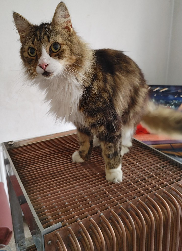
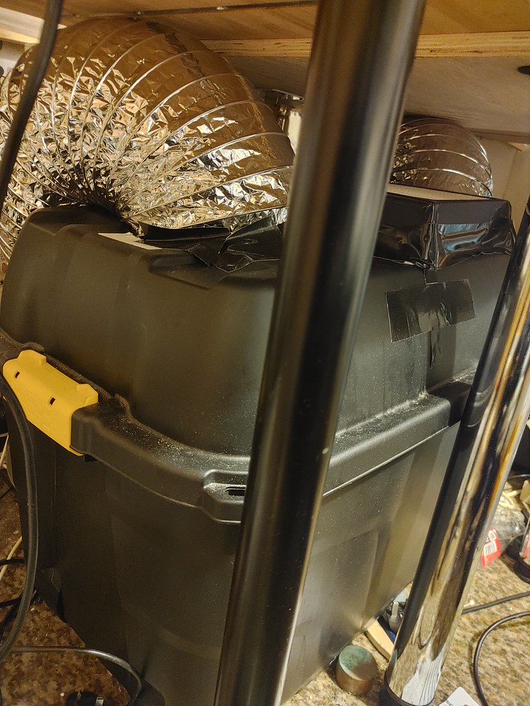
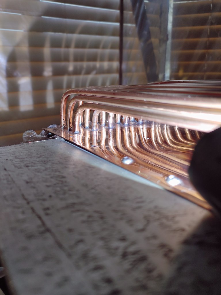
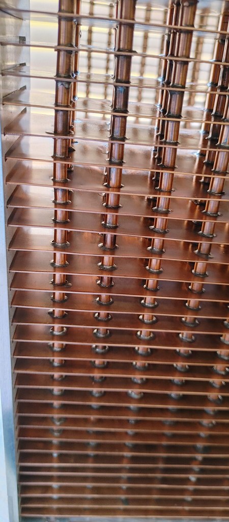
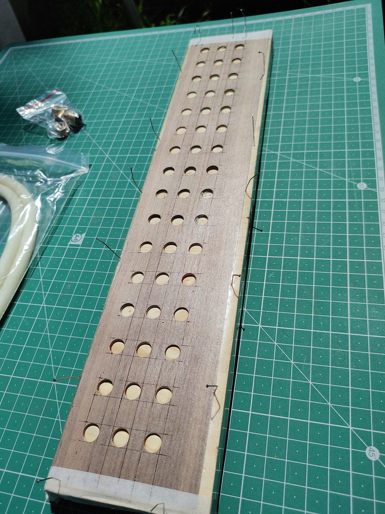
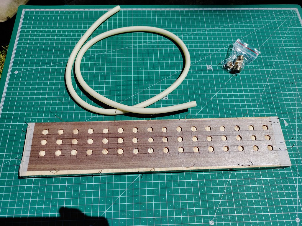
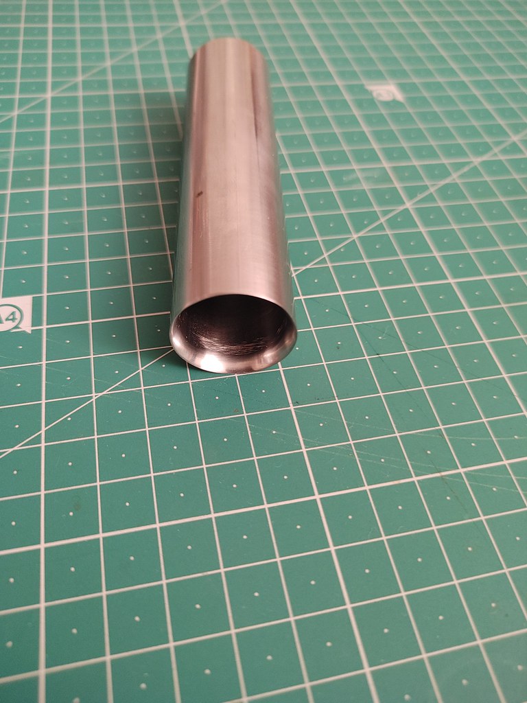
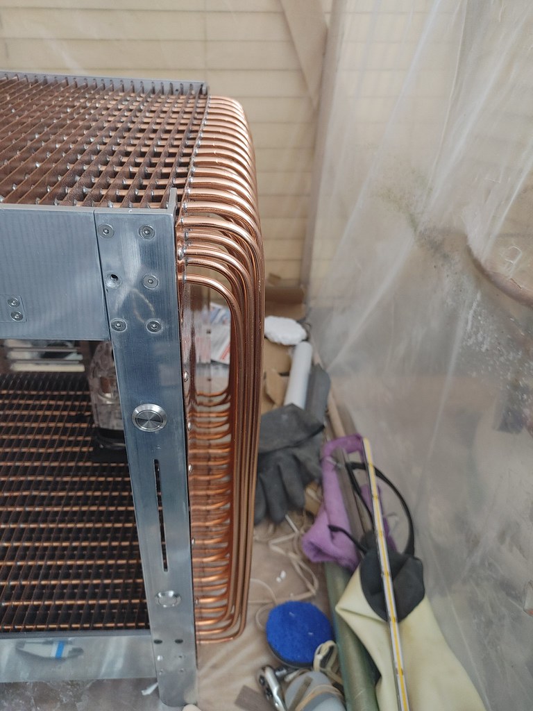
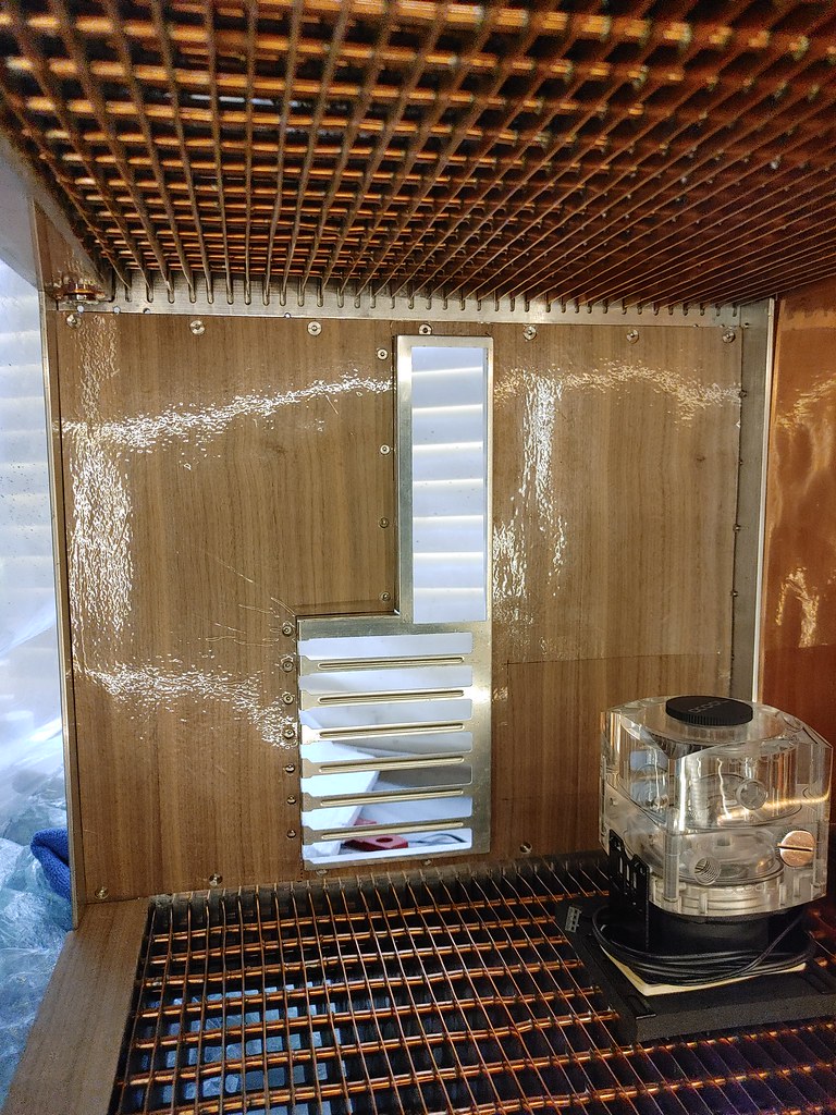
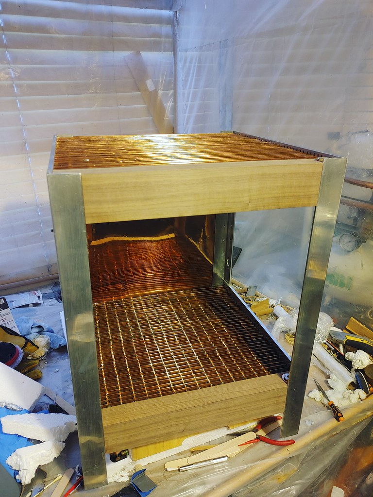
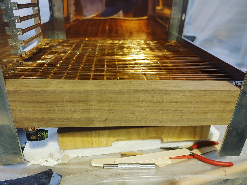
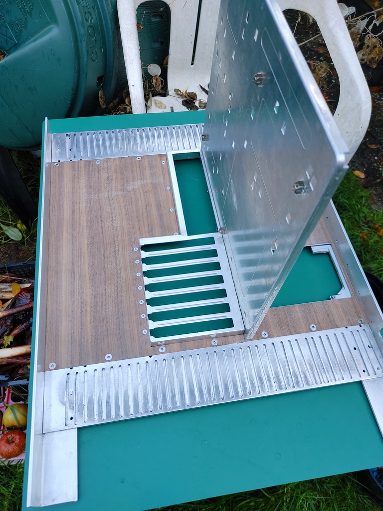
Last Summer when changing water in my loop I rediscovered this under a table, and for some unknown reason thought polishing it and finishing it would be a good idea. So what do we have?

20210719_175350_HDR by Tom ., on Flickr20210719_175552_HDR by Tom ., on Flickr

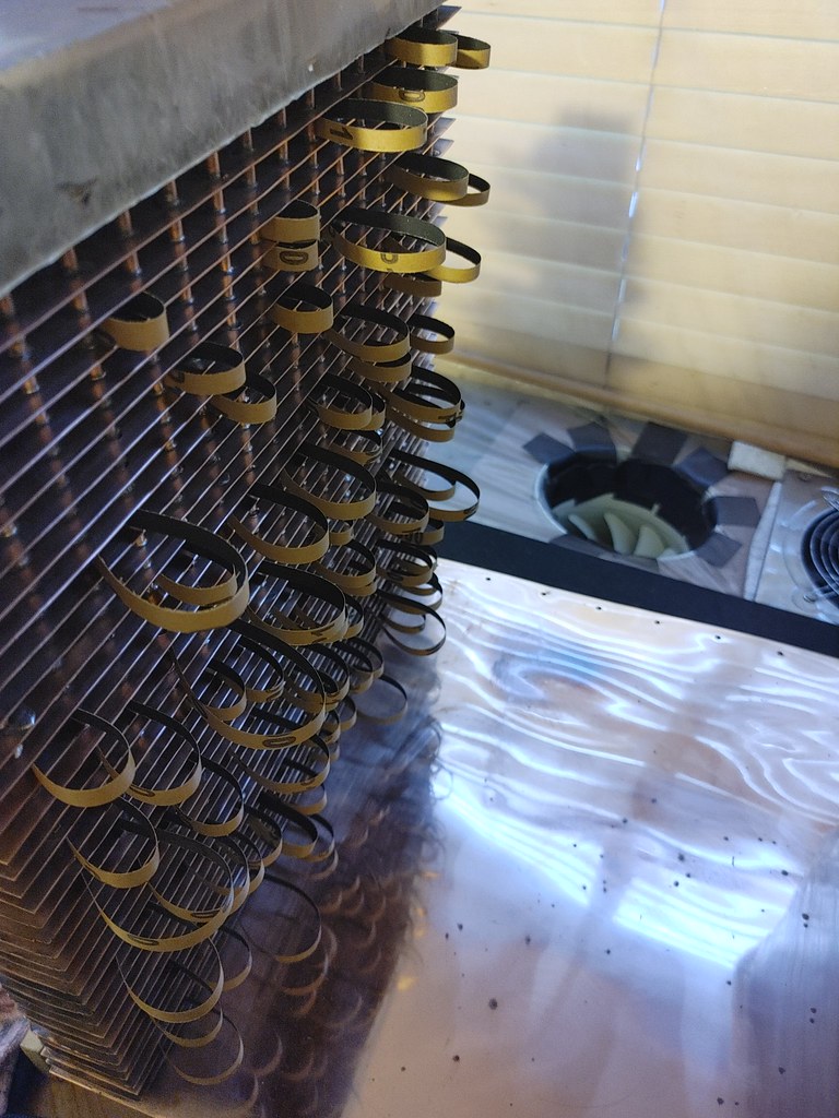
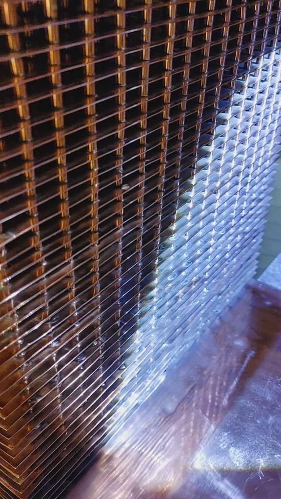
20210719_175647_HDR by Tom ., on Flickr

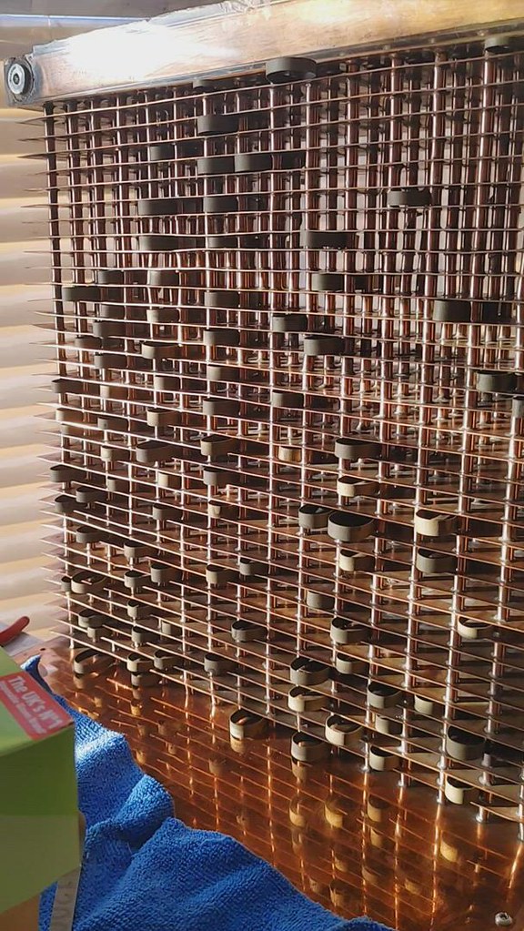
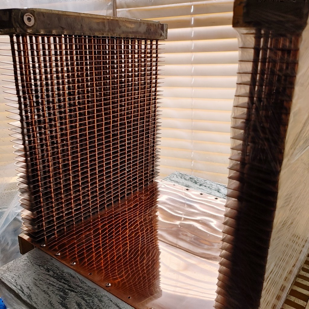
20210719_175559_HDR by Tom ., on Flickr

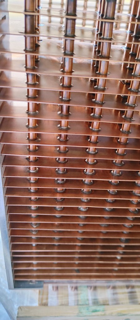
20210720_210723 by Tom ., on Flickr

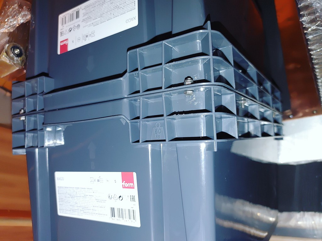
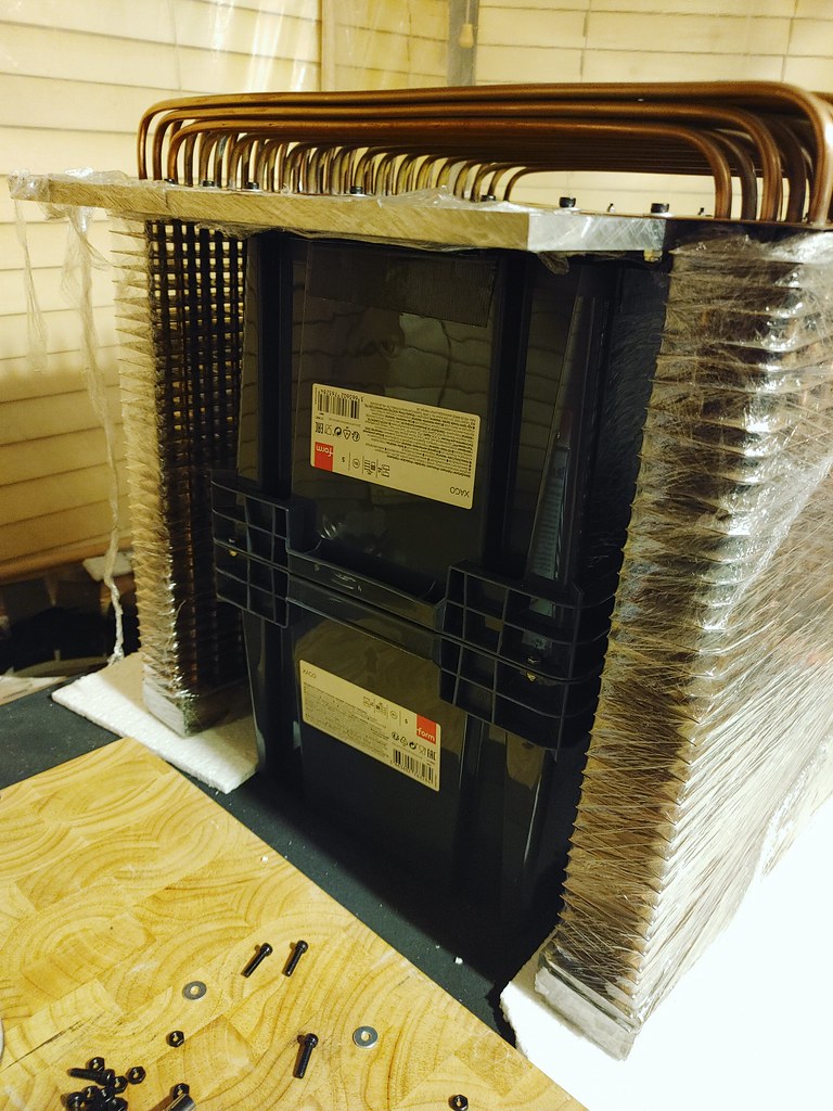
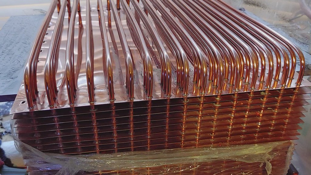
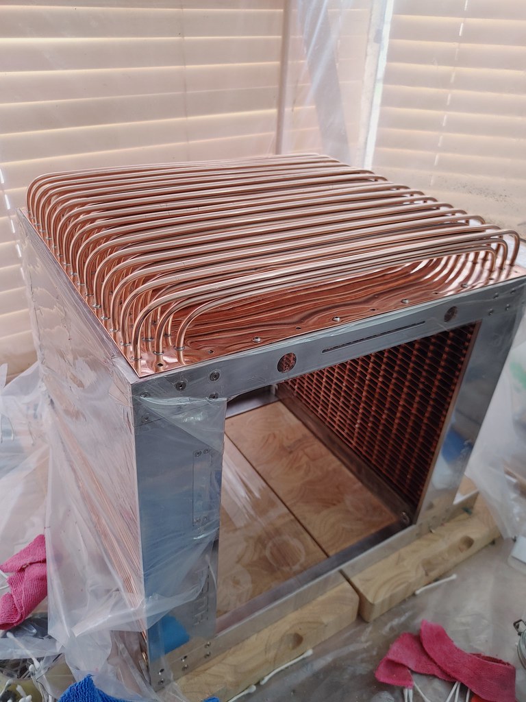
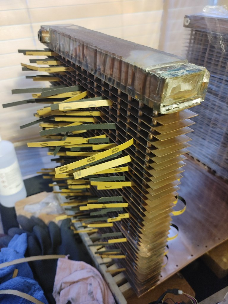
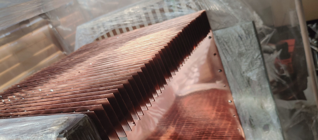
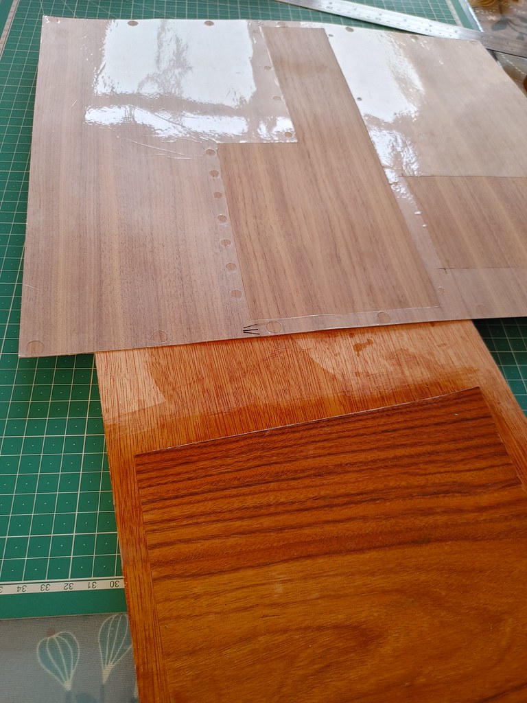
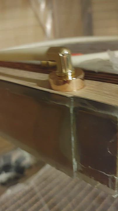
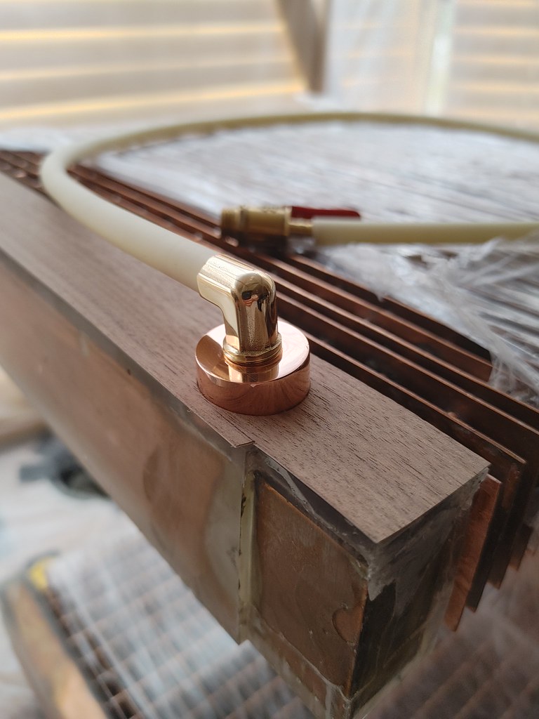
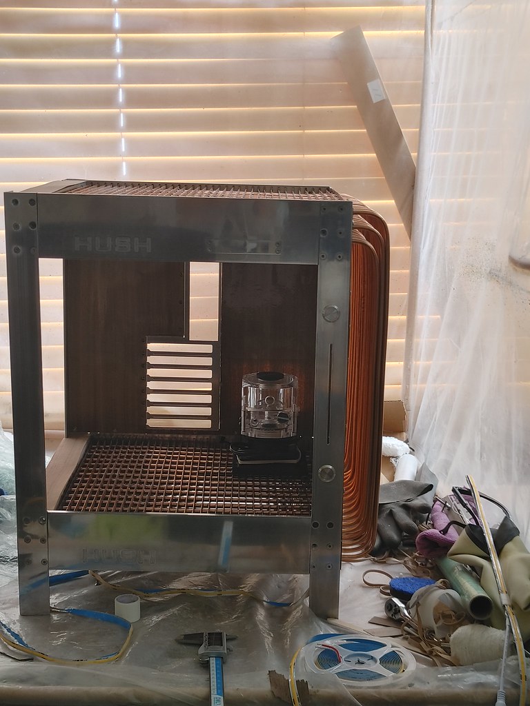
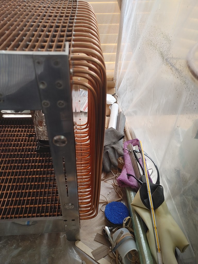
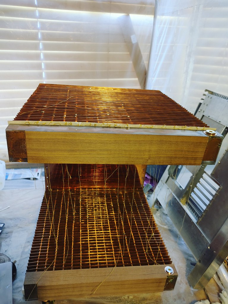
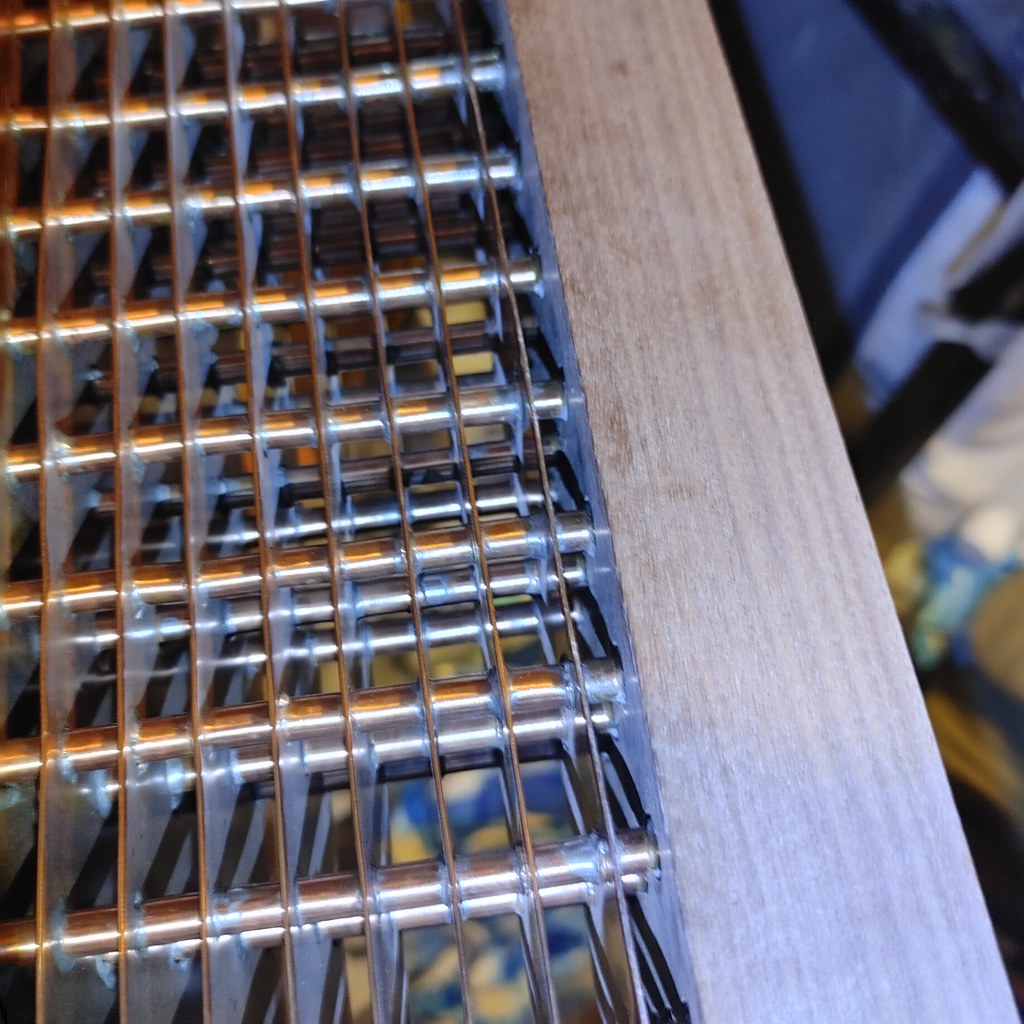
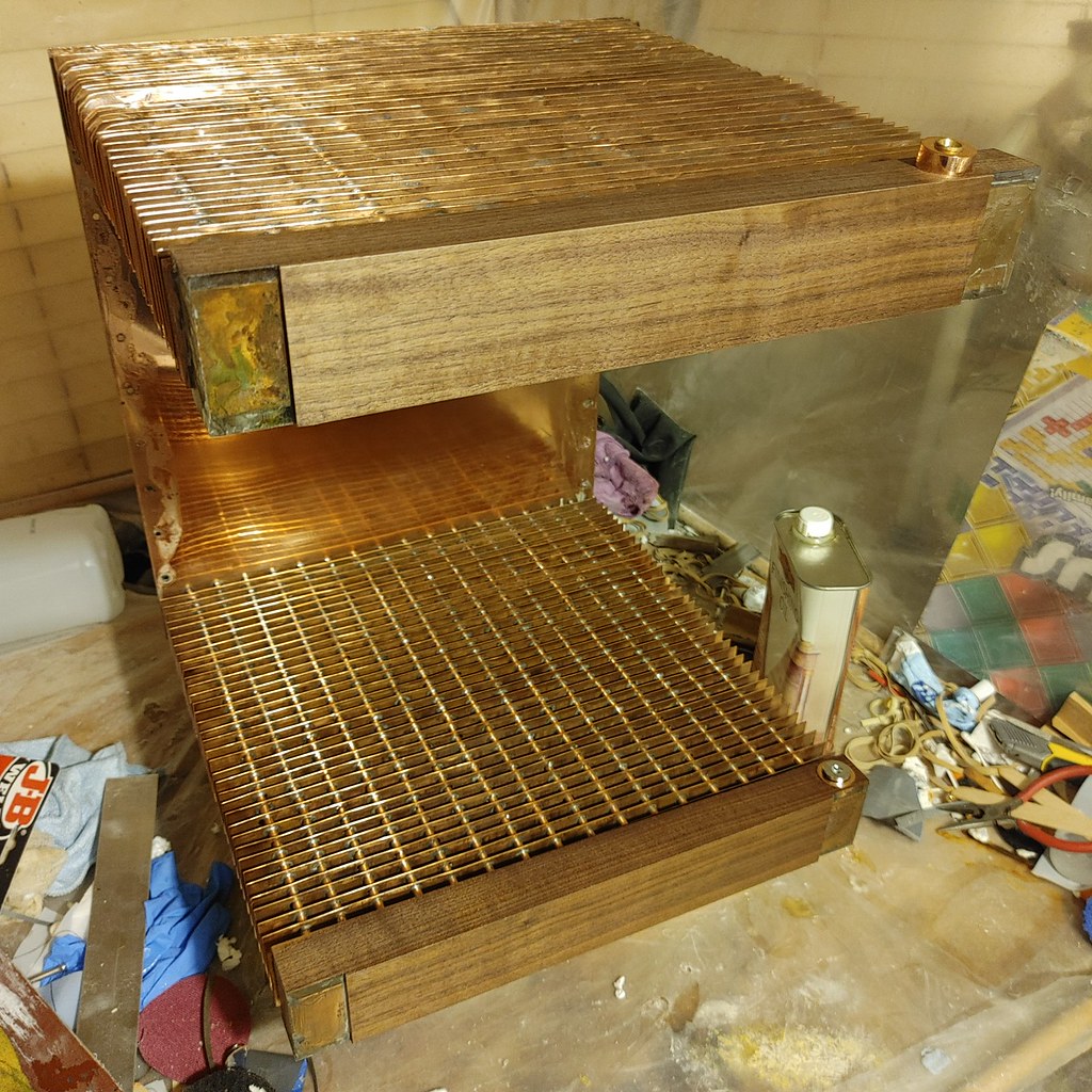
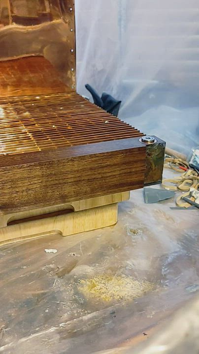
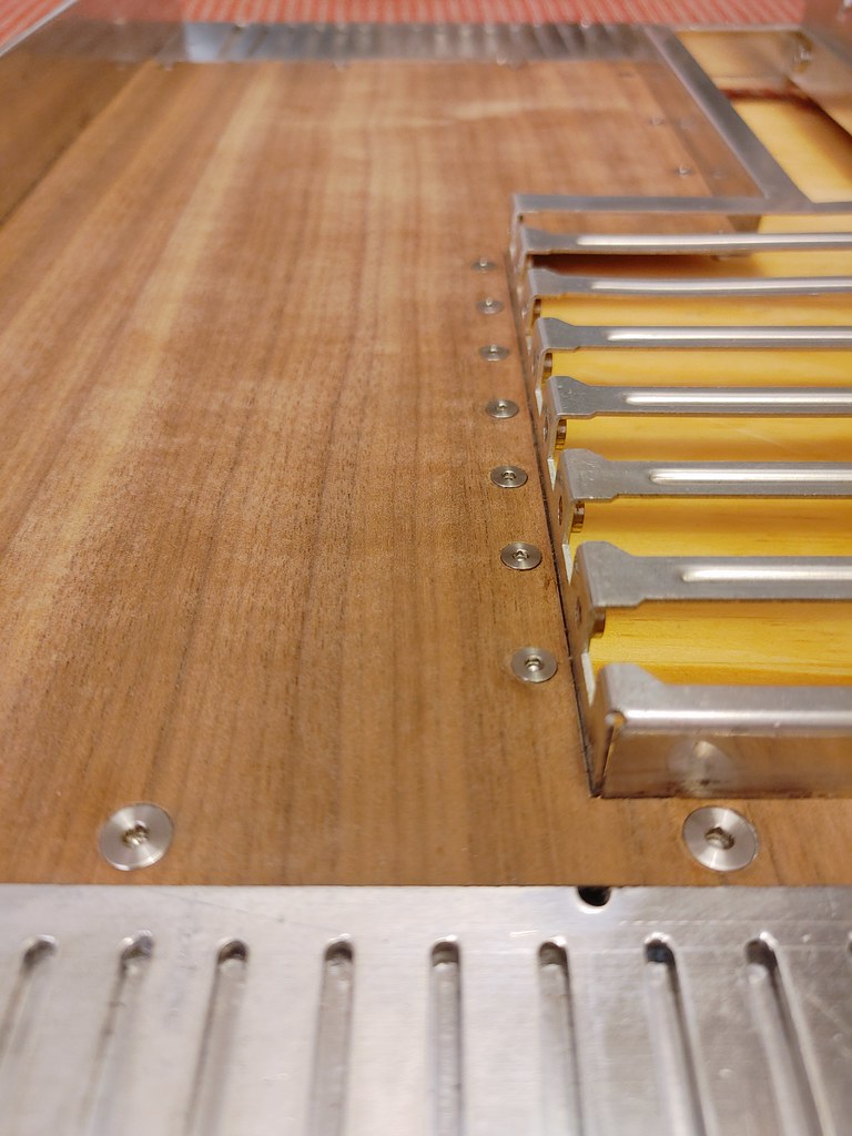
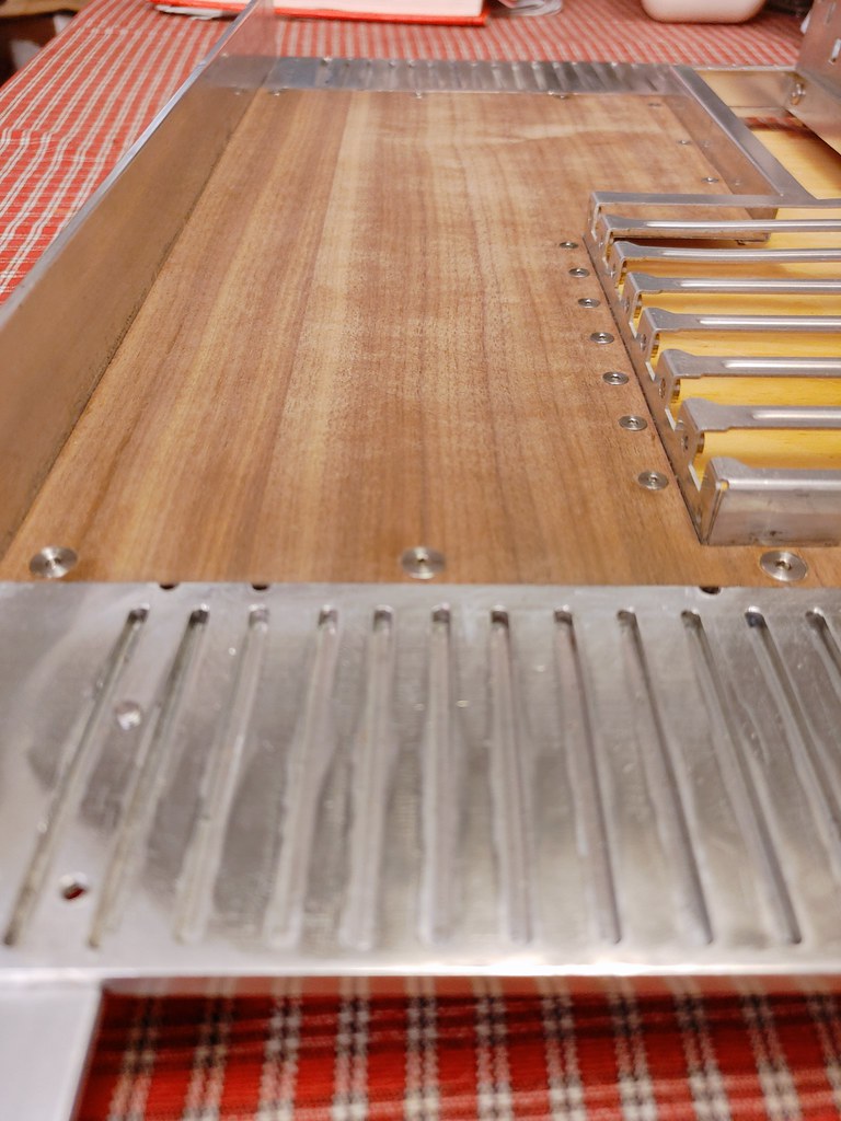
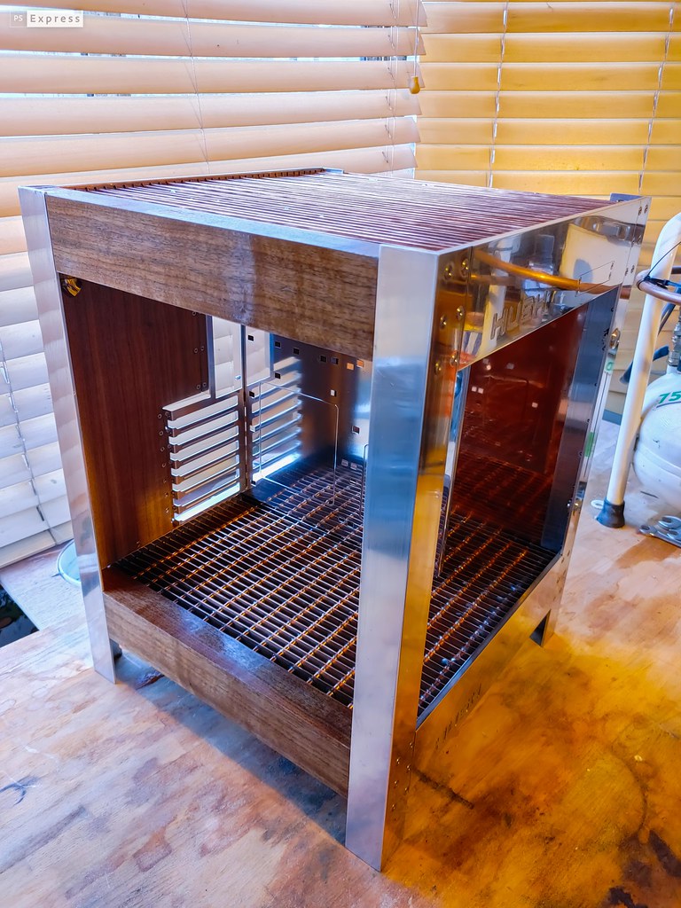
Some work is needed... Those dribbly gummy looking bits on the boxes at the end are polyester resin that was used to fill crinkled valleys left when originally casting the polyester for the water distributor boxes using acrylic sheet for the mold (the polyester resin pulled the protective sheet on the acrylic off as it set). That'll need sanding down...

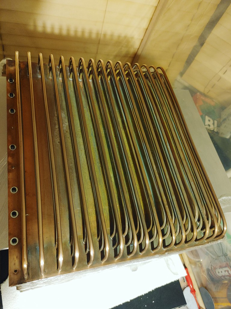
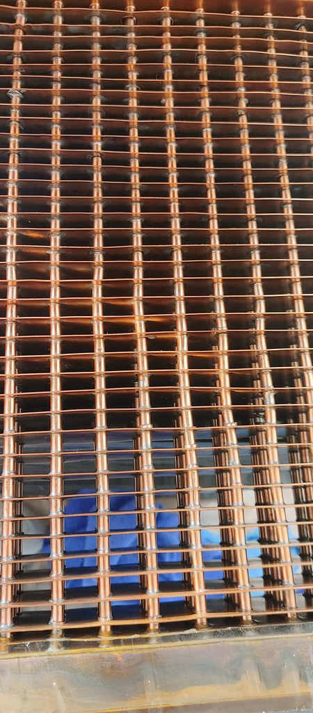
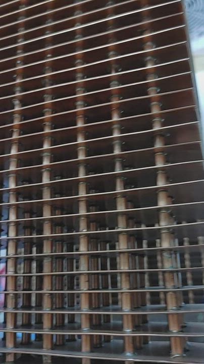
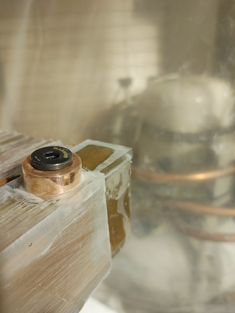
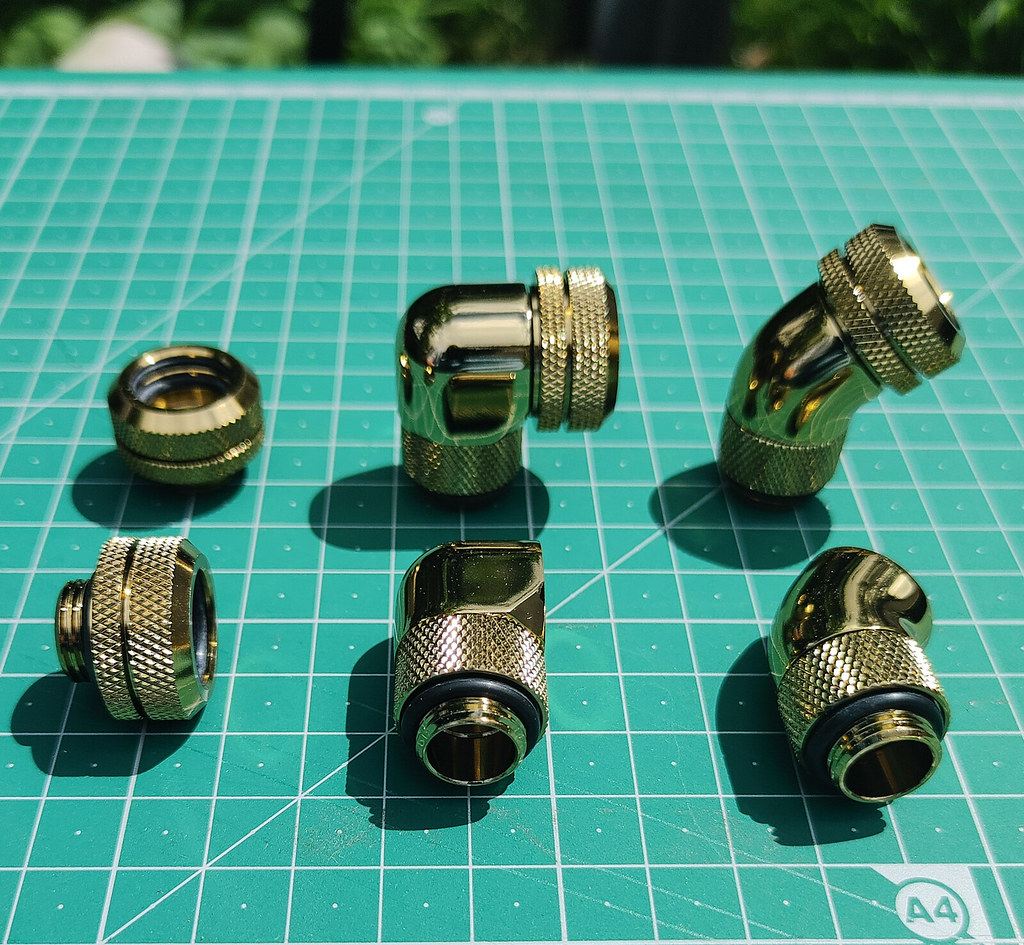
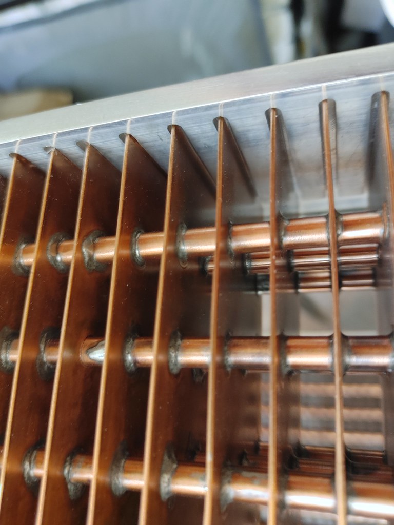
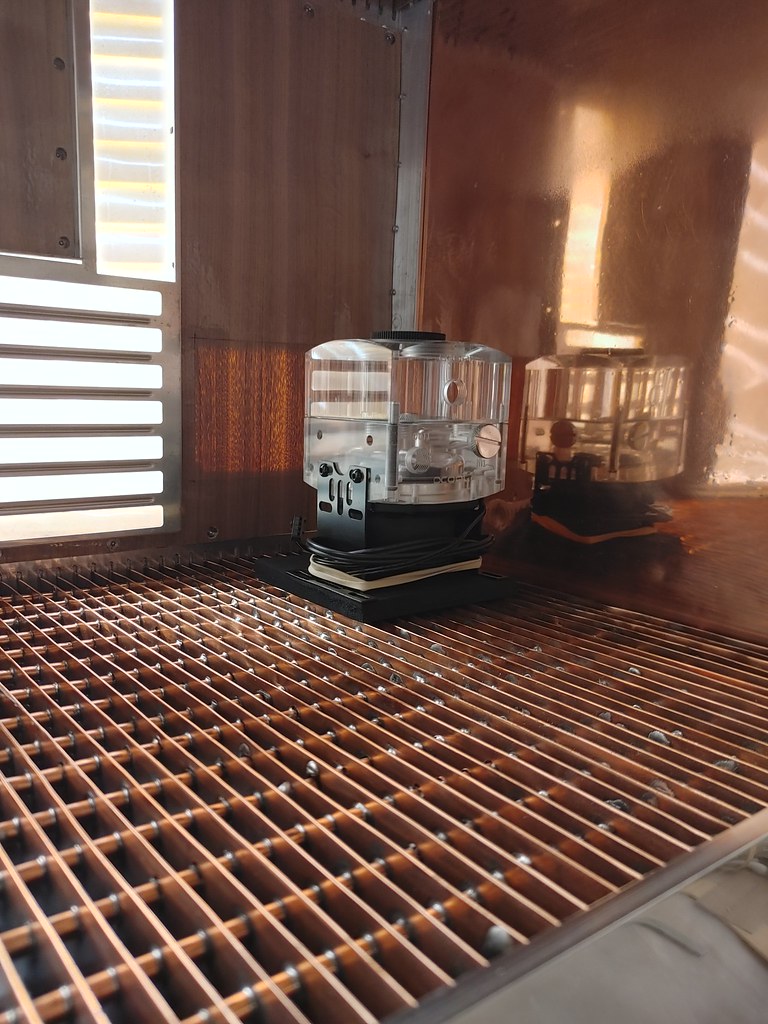
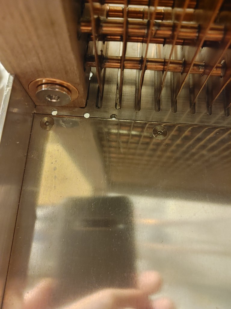
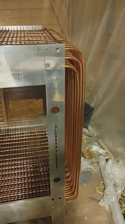
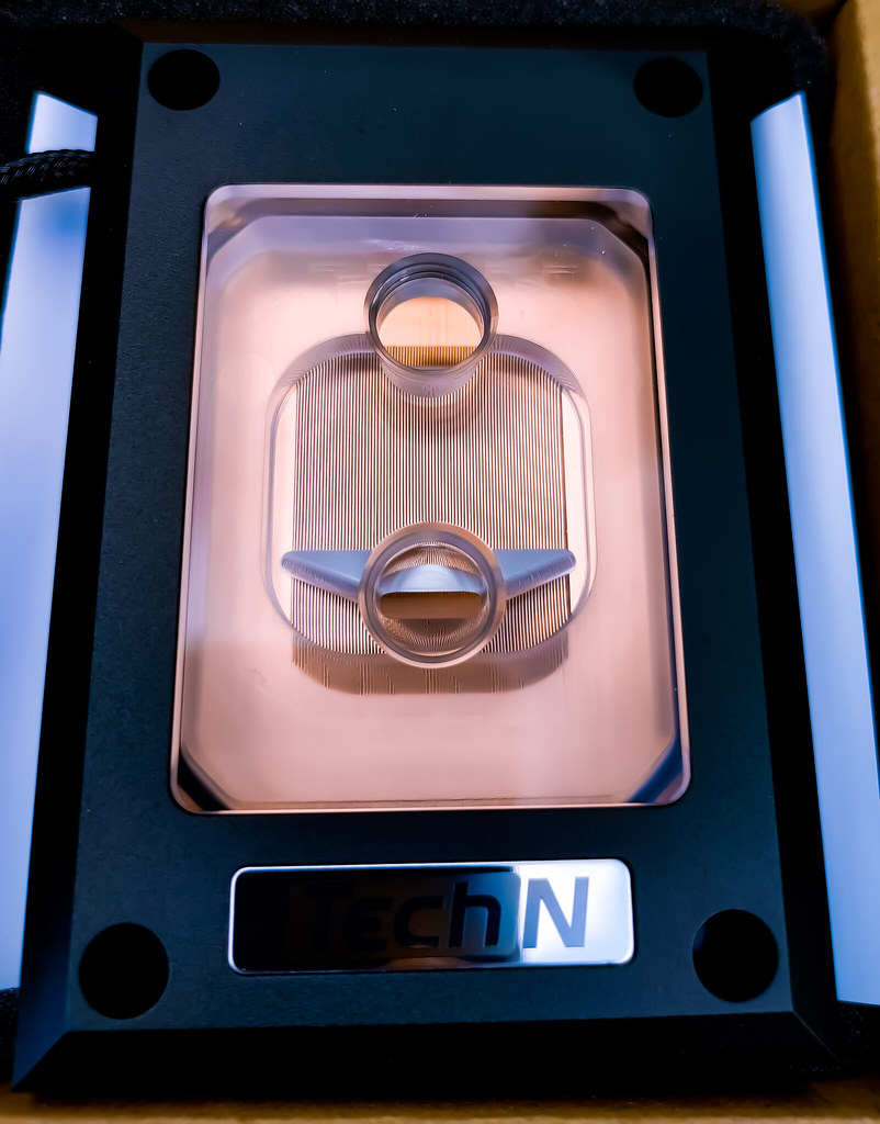
Polishing was tricky - it's an intricate design with pipes in the way and is difficult getting between the cooling fins and pipes....
 
Last edited:
Pro-tip: if you plan on polishing something to a near mirror shine (or as best as possible) do not first get it material blasted.

It's quite a large hefty case (don't be fooled by the scale from the cat, who is a large Maine C-oon cross). It weighs something like 25kg iirc without the aluminium frame, and the copper back wall would need supporting to sand easily with power tools. This calls for a jig!

Screenshots_2022-05-11-22-50-04

I constructed a wooden slatted support frame that the pipes on the copper wall would sit between and then slide in a supporting plate, to allow the copper wall to sit horizontal without the pipes scruffing, and a large 10mm thick plate of aluminium to be drilled for the copper wall to bolt down onto and rest on to keep it flat for sanding.

To get at the copper wall behind the copper pipes I used a 3" sanding disc rotary padworking up the grits of hook and loop attaching sanding paper discs (400, 600, 800, 1000, 1200, 1500, 2000 then polishing compounds on soft wool pads/mops then cellulose thinner to clean) powered by a variable speed drill. To get clearance to avoid the pipes, the sanding pad shank was replaced with a longer bolt with the same thread. To avoid the weight of the copper from damaging the polester resin covered end boxes I bolted two heavy duty polypropylene stacking boxes together to act as a table sitting inside to take the weight, with a neoprene pad cut around the PP crate shape/lattice, and taped in place to give friction to stop it sliding.

20211031_211556_HDR by Tom ., on Flickr

20211123_005727 by Tom ., on Flickr

20211123_005636 by Tom ., on Flickr

20211124_232137 by Tom ., on Flickr

20211121_154135 by Tom ., on Flickr

20211124_232152 by Tom ., on Flickr

20211125_205916 by Tom ., on Flickr

20211219_054205 by Tom ., on Flickr
 
Last edited:
The turquoise patina in those last shots was from trying to get the copper shiny chemically with a hydrogen peroxide containing liquid. That didn't work. Did look quite nice though in a way, but it's shiny we want!

20210822_175028_Edited by Tom .
 
Last edited:
It's a dusty business this sanding, and I'd need a spray booth for the lacquer. I made a spray booth with 12 x 1m long16mm diameter wooden poles, some cheapy cast aluminium 16mm pole corner connectors, some thick polypropylene 2m wide sheeting and heavy duty tape, and two cheap high speed 8" extractor fans, ducted to exhaust to a large 170 litre plastic storage trunk half-full of water (the idea being much of the dust would be caught by the water) with the air ducted down to flow across the water surface by sheets of thick polystyrene, exiting the top of the large box via a large hepa filter (~25cm x 35cm) , followed by an activated charcoal filter layer (both replacement filters for air filter units) added after that as final stage when needed for volatile organic compounds from cellulose thinner use and spraying). The wall of fans is 9 x gentle typhoons to blow across the sanding surface or help ventilate the room when needed.

20211101_101436 by Tom ., on Flickr


20211031_211803_HDR by Tom ., on Flickr

One of these and good ventilation still needed!

20211101_130618 by Tom ., on Flickr

20211101_130618
 
The rotary sanding disc/wool pads got the central bit up to a mirror shine. The tubes and between them on the copper wall part was done by wrapping fine grit sandpaper around a 6mm square bar of tool steel, and the pipes by using perhaps 2-3cm wide strips of microfibre cloth soaked in brasso and flossing the pipes wrapped between pipes like you'd imagine a system of pulleys.

20220124_125827 by Tom ., on Flickr

20220124_141258 by Tom ., on Flickr

YouCut_20220512_013031616 by Tom ., on Flickr

Click on pics above for videos.

20220404_181116_HDR by Tom ., on Flickr

20220327_165039 by Tom ., on Flickr

20220122_161833 by Tom ., on Flickr

20220122_161934 by Tom ., on Flickr
 
So, the back wall and pipes was tricky to polish with the sanding/polishing pads on the drill, and with polishing the pipes with sandpaper strips and brasso on strips of microfibre cloth. The radiator fins and pipes inbetween were another matter - the gaps are too small to get power tools in to sand easily, and flossing the copper pipes of the backwall involved 96 of them.


I had tried using sanding discs on a dremel to sand the radiator fins/plates near the surface, but the handmade slightly wonky nature of them from making the radiator meant they were often slightly off perfectly flat so this didn't really work very well.


I found this handy mole clamp- think it's meant for clamping for welding, but works very well for straightening wonky 0.9mm copper fins!

20211031_224433 by Tom ., on Flickr

The gap between the fins is around 9mm - I used sandpaper wrapped around a long 6mm square bar of tool steel to sand between the fins, and strips of sandpaper of p1000 or p1200 around 7-8mm wide, cut from standard 230mm x 280mm sheets of wet'n'dry paper with a paper guillotine.

20211112_162027 by Tom ., on Flickr

20220130_190612_HDR by Tom ., on Flickr

Not perfect, but the sanding with the wet'n'dry-wrapped bar did get the fins nice and pink in the centre.


It's actually quite quick to thread the wet'n'dry strips around the pipes, and the sanding for each one took maybe 10-15 seconds. There's 48 6mm diameter pipes running between each set of fins, and 74 fins in total, and sanding each needed sanding twice (up and then down from the other side. Thank God for podcasts and audiobooks: This took a while....

20211112_161905 by Tom ., on Flickr

20211112_161916 by Tom ., on Flickr

20220210_155437_HDR by Tom ., on Flickr

20220210_155125 by Tom ., on Flickr

20220228_134132 by Tom ., on Flickr

Below are videos:

20220216_015928 by Tom ., on Flickr


Video: - excuse the extractor fan noise!


20220217_224259 by Tom ., on Flickr

(shiny, noisy video!)

20220217_225553 by Tom ., on Flickr


That's all for now folks
 
Last edited:
20220124_125808 by Tom ., on Flickr

20220217_152030_HDR by Tom ., on Flickr

So after polishing everything it was time to spray it with Incralac lacquer to keep it shiny. I got a lovely second hand mini spray gun called the Iwata G6, thinking this would be better for a smaller more precise spray pattern to get between the fins and pipes, but unfortunately this didn't work for spraying lacquer - it's too thick for the small 0.6mm diameter nozzle size, causing cobwebbing (needing too high an air feed pressure and spraying dry strands as a result). I then got a cheap spray gun with a larger nozzle and it worked much better.


Wrapped up for spraying the pipes/back wall:

20220404_181116_HDR by Tom ., on Flickr


I don't have any pics of spraying, as it's all messy and a case of 'open window with fans blowing out, do spraying, seal up spray booth and leave room and shut door!'


After:

20220317_112454_HDR by Tom ., on Flickr

20220317_112518_HDR by Tom ., on Flickr

20220317_112522_HDR by Tom ., on Flickr

20220319_162236_HDR by Tom ., on Flickr

20220319_161132_HDR by Tom ., on Flickr

Videos:

20220317_112647 by Tom ., on Flickr

20220503_182206 by Tom ., on Flickr

20220319_162630 by Tom ., on Flickr
 
Next up is sorting out the 2 cast polyester-coated water distributor boxes that the 48 copper pipes connect to, at the top and bottom of the case. In making them originally, I had made a mold from acrylic sheet to cast the polyester resin, and the heat from the polyester resin had heated the protective sheet on the acrylic so much that it shrunk and caused wavy valleys in the cast polyester.

20220430_230310_HDR by Tom ., on Flickr

What looks like spiders webs there is scoring with a craft knife/scalpel to aid with the new resin bonding to the old.

20220506_211505_HDR by Tom ., on Flickr

20220507_012942_HDR by Tom ., on Flickr

20220507_012947_HDR by Tom ., on Flickr

20220507_160239_HDR by Tom ., on Flickr

20220507_012947_HDR by Tom ., on Flickr

The mold is acrylic panels, attached and sealed with silicone glue, or with Copydex (latex glue - much less nessy and easier to clean-up and remove afterwards). Holes and slots were blanked with Copydex or Bluetac where needed, and the aluminium rubbed with candlewax to aid release after casting.

20220513_185202_HDR by Tom ., on Flickr

20220515_045720_HDR by Tom ., on Flickr

Lots of bits needed recasting of resin to tidy up and then sand down to flat and sharp edges to then veneer with walnut (with pressure-sensitive adhesive backing). To get the veneer to sit flush with the copper ports the surrounding resin was sanded 0.4mm deeper than the ports, and similarly for the resin box sides to sit flush with the aluminium angle 'legs' of the supporting frame.


20220503_182137_HDR


To make sanding easier I made several plane sanding blocks by gluing a roll of p280 sandpaper to a large thick steel plate (~50cm x 15cm) and a smaller 1cm thick piece of aluminium plate.


20220529_224929_HDR


20220529_224929_HDR

20220505_194216_HDR


Sanding to get flat surfaces and sharp edges for tge veneer:


20220515_045720_HDR


20220513_185219_HDR


20220513_185202_HDR


Disassembled aluminium wall with IO/PCI slot bracket.

20220425_164457_HDR by Tom ., on Flickr


Below: Making a veneer skin for the wall the IO panel attaches to. I decided to make life difficult and cut holes for all the countersunk bolts, partly to keep the slightly industrial look of countersunk bolts, and partly to allow disassembly, and partly because I found a cheap manufacturer of grade 5 titanium bolts to replace the stainless steel ones, and machined titanium bolts are very attractive. To make the holes in the veneer I used hole-punches (8mm diameter for m4, and 6mm diameter for the m3 countersunk bolt heads). The next issue will be getting the countersunk bolt heads to sit flush with the ~0.4mm thick veneer - either with countersunk collars for the bolts or by sanding down the whole aluminium sheet by 0.4mm.


To mark out the hole positions etc for the veneer I used a sheet of low tack plastic adhesive sheet, which I could score the edges of the countersunk holes to cut the holes from the plastic sheet, then transfer to veneer to guide cutting and hole-punching. (On that board is a test veneer piece of rosewood stained with Shellac/French polish - didn't like the colour).

20220425_174310_HDR by Tom ., on Flickr

20220424_135249_HDR by Tom .

Large 25mm diameter hole punch for cutting holes in the veneer cladding for the copper g 1/4" BSP ports to poke through/sit flush with, on a test piece of veneer.

20220423_175214_HDR by Tom ., on Flickr

One of the veneer pieces to clad the resin boxes. Fiddly!


20220428_144829_HDR


Mock-up of the veneer on the top resin box - that's the fill-port with a gold plug screwed in. Quite finickity cutting the walnut veneer precisely - probably need to redo this one as I shaved off a little too much at the bottom right. I also need to sort out the gap in the aluminium sections by milling the thicker plate (it was unfortunately milled a little short for the step for the right-angle aluminium in the bottom right to sit flush, and is a little inaccurate anyhow)


20220430_134501_HDR by Tom ., on Flickr


Below: Early mock-up of unstained and unattached veneer panels for a rough view of how it will look.

20220430_134519_HDR by Tom ., on Flickr

20220430_134538_HDR by Tom ., on Flickr
 
Last edited:
Time to make the really fiddly bits of veneer - to cover the sides of the resin-covered manifolds/boxes that all the 48 copper water pipes connect into.


This is cut a little oversized in length and width atm to trim down after. The little drill bit pictured there is a paper drill bit - essentially a sharpened tube drill made for specific paper drills...


It's a little oversized at 9mm diameter to allow for resin meniscus that formed around each 6mm diameter copper tube when casting the resin manifolds

20220612_161121_HDR by Tom ., on Flickr


Sadly the paper drill bit has a funny tapered end for the specific paper drill (basically a proprietary bench drill), and the coloured collar in the middle was larger than the drill chucks of and bench and hand power drills I have, so I dremelled off the tapered part and ground down the coloured metal middle part with a micrometer to check it was parallel and would drill accurately.

20220612_220702_HDR by Tom ., on Flickr

I used low tack adhesive plastic sheeting to avoid marking the veneer. It's attached to a neoprene sheet in the above photo (to avoid mangling the paper drill bit), though I switched to using a piece of pine wood as a drill bed instead as drilling needed downward pressure and the neoprene didn't help here.


I stacked two pieces of veneer to drill both at the same time and save a bit of time, with pins to prevent the veneer moving about.


48 holes drilled for the copper pipes. This will then need to be cut into thin strips to thread between the rows of pipes, aligned and stuck down and stained with tung oil with a small paintbrush. That'll be fun.

20220614_130533_HDR by Tom ., on Flickr

I got a few pits in the mail from AliExpress - some little 1/4" BSP plugs to aid in spray lacquering the copper ports, and 1m of 1/4" ID cream Tygon A60F norprene tubing to use for the drain port as a valved tube tucked away, with a little baby ball valve on one end - should make draining the loop easier and less messy. I quite like the cream colour - should go well with the walnut I think for a slightly retro hifi look.


20220614_130643_HDR by Tom ., on Flickr


2nd coat of Tung oil on the test pieces - again most tung oil wiped off after saturating for 30 minutes - more coats needed.

20220614_130845_HDR by Tom ., on Flickr

Thanks for reading.
 
Time to slice up the veneer box sides for the side of the resin manifold the pipes pass though so it'll pass through the array of 48 pipes.


First few slits cut here were by cutting repeatedly along the cutting line to cut through, and aren't perfect - I switched after this photo to cutting by using the scalpel blade as a sort of pivoting guillotine and that allowed cutting in one strike and the rest are very clean.


20220616_161425_HDR by Tom ., on Flickr


20220616_211119_HDR by Tom ., on Flickr


Next up horizontal cuts to seperate the veneer into 2 halves, to pass from above and below the grid of copper pipes.


20220616_214328_HDR by Tom ., on Flickr


Shows better here:


20220616_214143_HDR by Tom ., on Flickr


And here. All the bits cut out are arranged on the white a4 sheet to position with a pair of tweezers when the two halves have been positioned. Looking forward to that. Adhesive plastic sheet still on the two veneer halves at the bottom (so cutting guide-lines still visible)


20220616_230049_HDR by Tom ., on Flickr


Thanks for reading.
 
Bit of progress - lots of small diamond filing of the resin manifolds (bit boring, no pics), and some sanding and polishing of the g1/4 bsp copper ports.


The case is upside down here - this is the drain port with an incompletely polished 1/4" right angle barbed connector with the 1m of 1/4" ID norprene drain pipe with a largely unsanded little 1/4" ball valve on the end. The norprene will be trimmed to around 35cm or so and the ball valve tucked away when finished.


Videos:


YouCut_20220618_221335882 by Tom ., on Flickr


YouCut_20220618_182149571 by Tom ., on Flickr


Photos:


20220618_181238_HDR by Tom ., on Flickr


20220618_181044_HDR by Tom ., on Flickr
 
Baby update. Going to do some needless modding to mount the laptop optical drive, so got what seems the best laptop slot-loading optical drive - a fast BD burner, the panasonic UJ265, since the mounting will be drive-specific so figured best to get a BD burner. Nice to see the drive has the standard push-to-make surface mounted switch seen on the bottom left at the front there (the dark circle with the orange rim with 4 solder points at the corners of a surrounding square - should be able to cold solder to these okay with thermally conductive adhesive solder paint to attach up a remote laptop drive button on the front of the case with a bulgin anti-vandal type button to operate the drive.


Panasonic UJ265:


20220622_185156_HDR by Tom ., on Flickr

20220622_185310_HDR by Tom ., on Flickr

Laptop drive lid taken off. 4 baby 1.6mm countersunk bolts holding the lid on. Below, 1.25mm drill bits x 2, countersunk 1.25mm centre drill bit, baby 1-6mm diameter tap-wrench with M1.6mm tap in place. Plan is to cut the top to show the drive innards, with a sheet of clear cast plexi, attached with longer m1.6 countersunk bolts I have to account for the plexi thickness.


20220622_190554_HDR by Tom ., on Flickr


Lasers and clear plexi, and lots of polished copper... What could go wrong?
 
Small update - made a sanding jig for the resin manifold boxes - they're sanded down, but even with sanding with large plate metal with sandpaper glued to it, it's difficult to get everything exactly square, what with copper ports in the way etc, so I made a thick steel jig that would clamp around to give a perfectly flat guide that I can sand down to to give flat and square resin plenums. Should help the walnut veneer to adhere better and stop delamination hopefully!


Bits used - some 3mm thick steel 21mm(iirc) x 500mm equal angle section x 2, centre drill with 3.2mm centre drill, some equal aluminium blocks lying around to mount the steel angle section, clamps to clamp the 2 bits of steel angle together (the steel angle will clamp at both sides of the resin to give a flat plane to sand down to) , m4 tap.


20220625_191618_HDR_(1) by Tom ., on Flickr


20220625_191655_HDR_(1) by Tom ., on Flickr


Clamped in place (very fiddly to clamp it all in place!), drilled and tapped;


20220626_135336_HDR by Tom ., on Flickr


One side of the jig/sanding guide-guard then needed cutting down to accommodate where all the copper pipes go through. This killed a large dremel diamond cutting disc and about a dozen grinding discs. Should hold up to a bit of inadvertent sanding when used as a sanding guide I guess!


20220626_165548_HDR by Tom ., on Flickr


Finished! Held with 2 m4 bolts, both sides tapped in m4 and level.


20220627_193132_HDR by Tom ., on Flickr


20220627_193211_HDR_(1) by Tom ., on Flickr

20220627_193309_HDR_(2) by Tom ., on Flickr
 
Did some sanding on the resin boxes/manifolds using the steel guide I made, using rotary sanding discs on a drill.


20220630_133137_HDR by Tom ., on Flickr


20220630_155453_HDR by Tom ., on Flickr

20220630_194139_HDR by Tom ., on Flickr


Quick mockup of the veneer, held down with sockets and spanner etc:


PSX_20220702_144235 by Tom ., on Flickr

And finally, received some trinkets and baubles in the mail... Shiny!

20220702_133446_HDR by Tom ., on Flickr

PSX_20220702_143216 by Tom ., on Flickr

PSX_20220702_142822 by Tom ., on Flickr

Thanks for reading.
 
A lot of this update is faff.


Cat decided not to supervise.


20220723_105151_HDR by Tom ., on Flickr


A 25mm outer diameter steel pipe...

20220707_220837_HDR by Tom ., on Flickr

A sharpened 25mm OD pipe for stamping holes in the veneer for the copper ports.

20220707_220842_HDR by Tom ., on Flickr

Gives a nice tight fit (video):

20220706_195153 by Tom ., on Flickr

I recast more resin on the top pipe manifold... Trying to get it so I can have this veneered manifold sit flush with the aluminium frame...


Blurry photo with cast resin on the top manifold up to the edge of the aluminium frame (if you squint hard enough it sort of looks like this).


20220707_225905_HDR by Tom ., on Flickr

20220707_225934_HDR by Tom ., on Flickr

And some sanding with the sanding guide/frame to get nice sharp edges - snowstorm:

20220711_224904_HDR by Tom ., on Flickr

I then needed to reattach the aluminium frame to check the cast resin level - still a mm to be taken off one side. The other side with this polished top fill port is more problematic - milling needed to tidy the 1/4" plate with 'HUSH' at the top to sit flush as the original milling for the aluminium angle leg to sit in and be bolted to it is off and needs extending by ~2mm, so new aluminium legs needed for the now repositioned countersink screw holes, new aluminium angle leg with the optical drive slit, as it sits too high atm (the drilled holes to bolt to the copper wall are 3mm of so too low on the legs, so the top edge sits too high and can't be milled to sit flush with the veneered manifold...


Fiddling around to get the fins at the top to sit high in the slots to try to get a flush fit at the top of the case between the aluminium frame and veneered manifold, a few mm would be milled off the top of the aluminium plate here...

20220717_133331_HDR by Tom ., on Flickr

Few pics of the case with lacquered polished pipes at the side - spraying this had been difficult - the structure of 16 rows of 3 pipes curving with a flat wall behind meant in ensuring all the polished copper pipes got covered that there ending up being a lot of overspray of lacquer on the flat copper back wall and orange peel, and some overspray on the pipes at the ends.

20220725_133608_HDR by Tom ., on Flickr

20220725_133600_HDR by Tom ., on Flickr

May be able to polish this down later to reduce hopefully, but regardless the pipes catch the light beautifully, giving a copper red glow in daylight and catching salmon-white on the pipe arrays in white artificial light, that doesn't show up that well on a phone camera...

20220725_134054_HDR by Tom ., on Flickr

20220725_132806_HDR by Tom ., on Flickr

20220726_013827_HDR by Tom ., on Flickr

On a brighter note (pun unintended) - I jerry-rigged some lighting in just held in place with some micropore tape (the lighting strips do have 3m adhesive backing for attachment- COB LED strips (direct mounted LEDs to a PCB strip allowing more LED density compared to usual LED strips - these are around 400 LEDs/metre with a silicone diffusing coating, so much more continuous bar or light rather than specular... I tried a square strip behind the front aluminium frame - quite difficult to see the LED light strips from normal viewing angles. A full square is probably a bit too much, though will be using some very thin lower wattage 2.7mm thick LED strips rather than these, which are 8mm wide with flexible PCB strip and contact points to the sides, so should be a bit less bright. I may remove the horizontal strip at the bottom and have strips under the radiator fins at the bottom front and back to give underlighting - the light bounces off the shiny pipes, but didn't get pics yet.

20220723_081630_HDR by Tom ., on Flickr

20220723_081901_HDR by Tom ., on Flickr

The shiny backwall gives a nice infinity radiator effect, but refpect the light strips....

20220723_081920_HDR by Tom ., on Flickr

20220723_080140_HDR by Tom ., on Flickr

The effect of underlighting under the fins looks really nice.

20220723_081846_HDR by Tom ., on Flickr


I added the veneered wall - still unattached and looking a bit hideous here as the low tack plastic sheeting is still on it, and the veneer is still unattached (as are the venner sheets for the manifold, that have gone a bit wavy in the recent heat and are unttached still so all a bit wonky..just to give a rough idea...

20220723_172100_HDR by Tom ., on Flickr

20220724_170804_HDR by Tom ., on Flickr
 
I've veneered the resin manifolds - a lot more work than I expected - had to sand and trim down the resin then make everything flat and even. I then polished and sprayed the ports to the radiator case with incralac acrylic lacquer to protect from corrosion, leak-tested and cleaned the inside of the radiator with oxalic acid solution, rinsed out with deionised water a few times, and then applied the pressure-sensitive adhesive veneer - here are all the pieces before going on:

20220927_233929 by Tom ., on Flickr

The comb like pieces there are for the resin manifolds that the 48 pipes go through, and a very tight fit to insert the past the pipes, so I used a scalpel to cut the backing plastic sheet on the veneer into small pieces and thread a pull cord to each of these pieces so I could then push the comb-shaped veneer pieces past the copper pipes and into position, pull all the threads to remove the backing sheet of the pressure-sensitive adhesive-backed walnut veneer and then press against the resin box.

20221001_090522_HDR by Tom ., on Flickr

The veneer pieces are applied and then you need to apply a lot of pressure with a rounded hard object. The edges are trimmed (I found a stanley knife blade easiest to do this) as exactly as possible to have as seamless an appearance as possible for the next piece of veneer.


All veneer pieces now on, and need to give it a day or two after application before finishing the wood - I'll experiment a little but I think probably a coat or two of tung oil then either polyurethane or gloss polyacrylic varnish as a topcoat to seal/waterproof.


Here's some pics and a vid at the end:

20221001_174130 by Tom ., on Flickr

20221002_183605_HDR by Tom ., on Flickr

20221001_174349 by Tom ., on Flickr

20221002_184303_HDR by Tom ., on Flickr

20221002_184519_HDR by Tom ., on Flickr

20221002_185324_HDR by Tom ., on Flickr

Video:

YouCut_20221002_192732601 by Tom ., on Flickr
 
October 2022 Update

Put the fiddly little pieces shown here between the pipes with tweezers.

20221003_201736_HDR by Tom ., on Flickr


Tricky to show and the torch gives a purplish colouration, but nice pretty seamless fit

20221003_195451_HDR by Tom ., on Flickr

I got these little brass p-clips for the drain hose, to go with the brass fittings.

20221003_201125_HDR by Tom ., on Flickr


Fitted the drain pipe:

20221003_201209_HDR by Tom ., on Flickr

20221003_201614_HDR by Tom ., on Flickr

20221003_201637_HDR by Tom ., on Flickr
 
November 2022 update

First coat of Liberon Finishing Oil applied to most sides of the walnut. Takes a few coats to really start to get depth to the finish and a degree of gloss.

20221016_183656 by Tom ., on Flickr

20221016_183641 by Tom ., on Flickr

20221016_183605 by Tom ., on Flickr

Added some more liberon finishing oil to the walnut veneer - up to 2 or 3 applications and starting to get some depth in this short video:

20221018_170514 by Tom ., on Flickr

I enlarged the PSU cutout of the aluminium wall (the one with the motherboard IO and PCI bracket cutout) so it can be used to slide the PSU in from the back of the case as an option, but have a veneered flush panel that should be pretty invisible with the PSU attached to the back of the case. It'll maybe have the cables from the PSU feed through the panel if I can't feed them through a billet motherboard tray.

20221021_171910_HDR by Tom ., on Flickr


When I made the 1.5mm thick aluminium wall, the countersunk screws were drilled flush with the surface, so adding the 0.6mm thick veneer left it sitting above the screws and the 1/4" thick aluminium frame (the plates with the 37 slots in for the copper fins to sit in. I sanded down the aluminium wall by ~0.6mm with 3" sanding discs on a drill attachment to leave the countersunk screws flush with the walnut veneer.


20221025_194226_HDR by Tom ., on Flickr


I attached the veneer to the aluminium wall. Wish I'd found the razor thin paper hole drill bits when doing the veneer for the aluminium wall - the punches I used were inaccurate to position precisely, and some of the holes were off.

20221103_154808_HDR by Tom ., on Flickr


So I repaired the inaccuracies with the paper hole drill bits, and replacing the gaps with tiny crescents of veneer, matching the grain as best I could from scrap veneer pieces.


20221103_154851_HDR by Tom ., on Flickr


20221103_155407_HDR by Tom ., on Flickr


20221105_180157_HDR by Tom ., on Flickr


20221105_180245_HDR by Tom ., on Flickr


20221106_144008_HDR by Tom ., on Flickr


20221106_144015_HDR by Tom ., on Flickr


There's a little bit of filing and tidying up to do. Here's the aluminium frame and wall, with motherboard tray. This mobo tray is too big and ugly, so will be replaced or possibly cut down.


20221106_144205_HDR by Tom ., on Flickr


But it's difficult to resist putting in the new hardware and running the pc - have had a gtx4090 sat in it's box for ~3 weeks, have a lovely CPU block from techN (ignore the moiré from the camera - in person the channels are perfectly straight and even).

PSX_20221106_165719 by Tom ., on Flickr


M.2 SSDs


20221106_142935_HDR by Tom ., on Flickr


7950x CPU and Asus x670e Crosshair Hero motherboard


20221106_143136_HDR by Tom ., on Flickr


Will likely measure up the aluminium wall etc for some machined bits to be made and put in the system for some testing and gaming! Looking forward to just running the 7950x cpu in the loop to see how it does!


Thanks for reading.
 
Update

Couldn't help tinkering a bit more before putting pc hardware in.

Tidied up the alternative orientation PSU hole with sone dremelling/filing and sanding. Cut and installed some rubber spacer strip between the aluminium angle legs and the veneered backwall, and drilled/countersunk 8 holes to give more structural tigidity and some vibration dampening. Made things shiny.

Bought a vertical GPU bracket that bolts to the usual pci bracket slot. It's 2 slots max, and the gtx4090 I have is 3 slots, so will need to wait until I receive the GPU block with replacement 2 PCI slot bracket before taking a dremel to the aluminium PCI bracket of the IO panel. Bought a coolermaster vertical PSU mounting bracket.

Here's the backwall/frame, with the 'alternative PSU orientation' hole open.

PSX_20221201_231915 by Tom ., on Flickr

Really must break out the full-frame DSLR and take some better photos, as my phone camera really struggles in low light and the noise reduction smears details!

PSX_20221201_234912 by Tom ., on Flickr

PSX_20221201_234350 by Tom ., on Flickr

PSX_20221201_232600 by Tom ., on Flickr

Thanks for reading.
 
Top